Chapter 2: Installation

2-7 Connecting Cables

Power Connectors

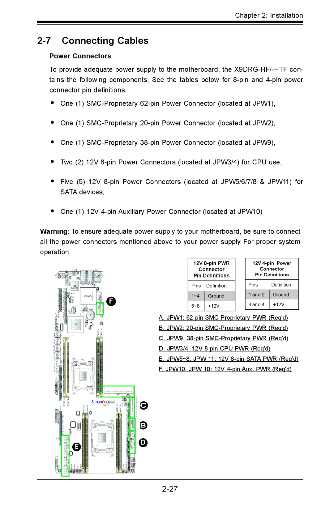
To provide adequate power supply to the motherboard, the X9DRG-HF/-HTF con- tains the following components. See the tables below for 8-pin and 4-pin power connector pin definitions.

One (1) SMC-Proprietary 62-pin Power Connector (located at JPW1),

One (1) SMC-Proprietary 20-pin Power Connector (located at JPW2),

One (1) SMC-Proprietary 38-pin Power Connector (located at JPW9),

Two (2) 12V 8-pin Power Connectors (located at JPW3/4) for CPU use,

Five (5) 12V 8-pin Power Connectors (located at JPW5/6/7/8 & JPW11) for SATA devices,

One (1) 12V 4-pin Auxiliary Power Connector (located at JPW10)

Warning: To ensure adequate power supply to your motherboard, be sure to connect all the power connectors mentioned above to your power supply For proper system operation.

F

12V 8-pin PWR

Connector

Pin Definitions

Pins Definition

1~4

Ground

5~8

+12V


12V 4-pin Power

Connector

Pin Definitions

Pins


Definition

1 and 2


Ground


3 and 4


+12V


A.JPW1: 62-pin SMC-Proprietary PWR (Req'd)

B.JPW2: 20-pin SMC-Proprietary PWR (Req'd)

C.JPW9: 38-pin SMC-Proprietary PWR (Req'd)

D.JPW3/4: 12V 8-pin CPU PWR (Req'd)

E.JPW5~8, JPW 11: 12V 8-pin SATA PWR (Req'd)

F.JPW10, JPW 10: 12V 4-pin Aux. PWR (Req'd)

A

E

C

B

D

2-27

Page 51
Image 51
SUPER MICRO Computer X9DRG-HTF, X9DRG-HF user manual Connecting Cables, Power Connectors