Chapter 2: Installation
Front Control Panel Pin Definitions
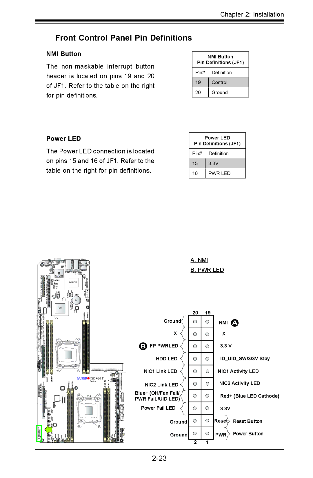
NMI Button
The
Power LED
The Power LED connection is located on pins 15 and 16 of JF1. Refer to the table on the right for pin definitions.
NMI Button
Pin Definitions (JF1)
Pin# Definition
19Control
20Ground
Power LED
Pin Definitions (JF1)
Pin# Definition
153.3V
16PWR LED
| LE4 |
|
|
| USB/0/1 | ||
SW1 S/IO | JVGA1 |
|
|
| |||
| JWD1 | JPB1 | JPG1 |
|
|
| |
|
| JCOM1 |
| JLAN2 | JLAN1 | IPMI LAN | |
|
|
| JPL1 | ||||
|
|
|
|
| |||
JPCIE6 | JPCIE5 | BMC CTRL |
|
| PHY | ||
J30 | DM1 |
|
| ||||
LAN CTRL | JTPM1 | ||||||
DM2 | |||||||
J29 |
|
|
| ||||
JI2C2 |
|
|
| ||||
JI2C1 |
|
|
| ||||
| BIOS | JPME1 | JPBR1 Battery | JPW10 | |||
JBT1 |
| ||||||
| PCH | JOH1 | JRK1 | ||||
JSD1 |
|
|
| JSPK1 |
| ||
A.NMI
B.PWR LED
A0AT |
| JWP1 |
|
| ||
|
|
|
|
| ||
|
|
|
|
| ||
|
|
|
|
| ||
JPCIE1 |
| CPU1 |
|
|
| |
|
|
|
|
| ||
|
|
|
|
|
| |
|
|
|
|
| ||
X16 |
|
|
|
|
| |
FANC |
|
|
|
|
|
|
|
|
|
| JPW1 |
|
|
|
|
|
|
|
|
|
|
|
|
| Rev. 1.20 |
|
|
| FANHFANG | JPCIE3 | JPW9 | |||
SGPIO1 | CPU1 Slot2 |
|
| CPU2 | CPU2 Slot 3 | JPW2 |
|
|
| ||||
| 3.0 X16 | J21 1 |
|
| 3.0 X16 | JPW4 |
|
|
|
| |||
|
| JPW 1 |
|
| JPCIE4 |
|
|
| JPW8 |
|
| CPU2 Slot4 | JPW3 |
|
|
|
|
| ||
JF1 |
|
|
|
|
| FANF |
|
|
|
| 3.0 X16 | ||
|
|
|
|
| ||
LE1 | FAN4 FANA FANB JL1 JPW5 | FAN3 | FAN1 FAN2 | FANE | ||
Ground![]()
X
BFP PWRLED ![]()
HDD LED
NIC1 Link LED ![]()
NIC2 Link LED
Blue+ (OH/Fan Fail/
PWR FaiL/UID LED)
Power Fail LED
Ground
Ground
20 19
2 1
NMI A
X
3.3 V
ID_UID_SW/3/3V Stby
NIC1 Activity LED
NIC2 Activity LED
Red+ (Blue LED Cathode)
3.3V
Reset Reset Button
PWR Power Button