X9SPU-F Motherboard User’s Manual
2-4 Motherboard Installation
All motherboards have standard mounting holes to fit different types of chassis. Make sure that the locations of all the mounting holes for both motherboard and chassis match. Although a chassis may have both plastic and metal mounting fas- teners, metal ones are highly recommended because they ground the motherboard to the chassis. Make sure that the metal standoffs click in or are screwed in tightly. Then use a screwdriver to secure the motherboard onto the motherboard tray.
Tools Needed
Philips Screwdriver | Philips Screws | Standoffs |
KB/MS | JPUSB1:B/P USB WAKE UP | JPUSB1 | |
|
| ||
USB4/5/IPMI_LAN |
|
| |
| MH3 |
|
|
|
| JPUSB1 |
|
| 1 | 4 |
|
COM1 |
|
|
|
COM1 |
|
| JTPM |
R137
JPG1 VGA
J5
| 1 | 3 |
JSTBY1 | 3 | |
1 |
| |
JPG1 |
| |
1
1
1
JPL2 JPME1
JPL1 JPME2
+
SPEAKER JSPK: Buzzer/Speaker SPKR1
J16
| JSPK | COM2 |
JPL1 LAN1 | JPME1 ON:ME RECOVERY OFF:NORMAL | JPME2 ON:ME MANUFACTURING MODE OFF:NORMAL |
CLEAR |
|
|
JUSB4 | JWD | JWD | JPI2C:PWR I2C |
|
|
| JPI2C | ||
|
| J31 | ||
JLED | J29 | MH4 |
| |
|
| |||
| JLED:Power LED |
|
|
|
NM XI | LED |
PW |
JF1 20
|
|
|
| CPU |
|
|
|
| J1 |
LED 1 | 2 | OH/F | F |
|
PF | FAIL |
| ||
RHD D NI CNI | CUID | PS RST | ON PWR | |
|
|
|
| 1 |
1
JPW1
FAN1
MH6
FAN2![]()
JPW2
| VGA | |||
| J28 |
|
|
|
|
|
|
| LAN1 |
|
|
|
| |
|
|
|
| |
|
| |||
|
|
|
| JLAN1 |
CMOS JBT1 |
JF1
![]()
![]() +
+
B1
MAC CODE
JRF1 RT11-2:AUTO JRF1 1 3
|
| JLAN2 LAN2 |
|
|
| 7 |
|
LE5 A | SW1 | 1 |
|
|
| ||
C |
|
|
|
LED |
|
|
|
| MH8 |
|
|
|
|
| J8 |
J4 |
| JI2C1/JI2C2 ON:Enable OFF:Disable |
|
|
| JI2C1 | 1 |
|
| JI2C2 | 1 |
|
|
|
UIOP
|
|
|
|
|
|
| REV:1.00 |
| CODE |
|
LE7 | A C |
|
|
|
|
|
| BAR |
| |
| JSD1:DOM PWR | GND GND 5V | C768 | JSD1 |
|
|
| |||
| 1 |
|
|
| ||||||
| 3 |
|
|
| ||||||
|
| SATA0I- | MH2 | |||||||
|
|
|
|
|
|
|
|
|
| |
| SBX2: |
|
|
|
|
|
|
|
|
|
|
|
|
| J2 |
|
|
|
|
|
|
|
|
|
|
|
| SBX1: |
|
| ||
|
|
|
|
|
|
| JL1:CHASSIS INSTRUSION |
|
| |
|
|
|
|
|
|
| JPB:BMC | |||
|
|
|
|
|
| JPB |
|
|
| |
DDR3 1600/1333/1066 UDIMM/RDIMM required
DIMMA1
DIMMA2
DIMMB1
DIMMB2
J3
| SBX3: | |
J15 | USB 12/13 | USB |
MH7
JUSB3
11
FAN3
|
| MH5 |
|
| 4 |
C |
| FAN5 |
LE3 LE4 C C | A A | |
LE2 | A |
|
JL1 |
10
1
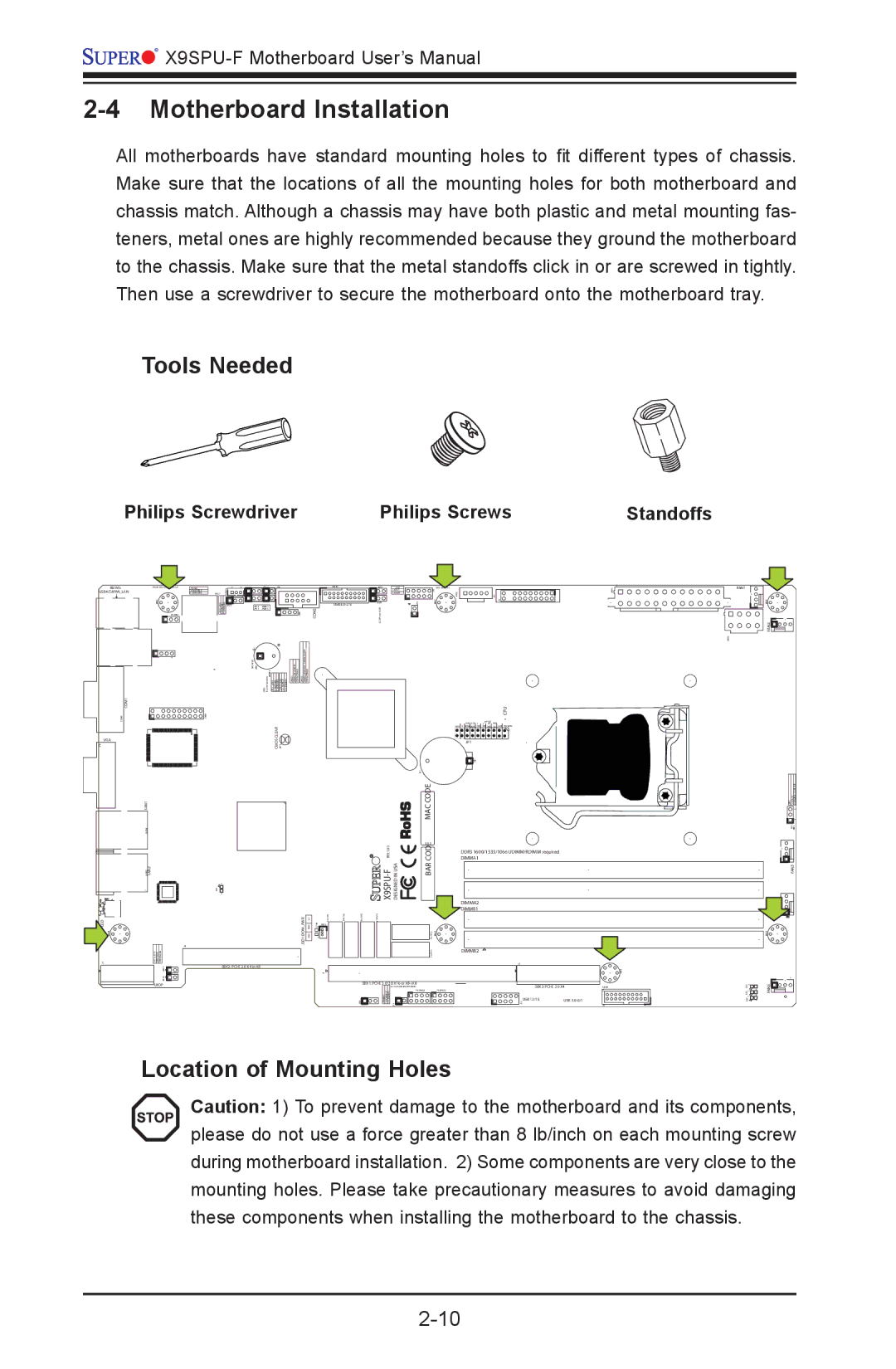
Location of Mounting Holes
Caution: 1) To prevent damage to the motherboard and its components, please do not use a force greater than 8 lb/inch on each mounting screw during motherboard installation. 2) Some components are very close to the mounting holes. Please take precautionary measures to avoid damaging these components when installing the motherboard to the chassis.