Chapter 2: Installation
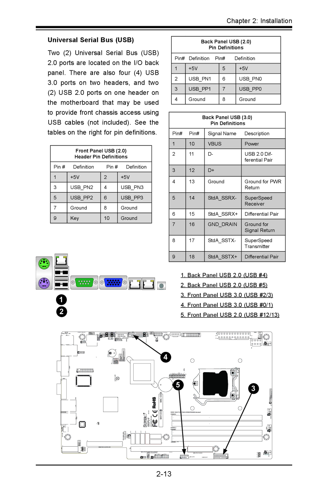
Universal Serial Bus (USB)
Two (2) Universal Serial Bus (USB)
2.0ports are located on the I/O back panel. There are also four (4) USB
3.0ports on two headers, and two
(2) USB 2.0 ports on one header on the motherboard that may be used to provide front chassis access using
USB cables (not included). See the tables on the right for pin definitions.
Front Panel USB (2.0)
Header Pin Definitions
|
|
| Pin # |
|
| Definition | Pin # | Definition |
| |||||||||||
|
|
|
|
|
|
|
|
|
|
|
|
|
|
|
|
|
|
|
|
|
|
|
| 1 |
|
|
| +5V | 2 |
| +5V |
| |||||||||
|
|
|
|
|
|
|
|
|
|
|
|
|
|
|
|
|
|
|
|
|
|
|
| 3 |
|
|
| USB_PN2 | 4 |
| USB_PN3 |
| |||||||||
|
|
|
|
|
|
|
|
|
|
|
|
|
|
|
|
|
|
|
|
|
|
|
| 5 |
|
|
| USB_PP2 | 6 |
| USB_PP3 |
| |||||||||
|
|
|
|
|
|
|
|
|
|
|
|
|
|
|
|
|
|
|
|
|
|
|
| 7 |
|
|
| Ground | 8 |
| Ground |
| |||||||||
|
|
|
|
|
|
|
|
|
|
|
|
|
|
|
|
|
|
|
|
|
|
|
| 9 |
|
|
| Key | 10 |
| Ground |
| |||||||||
|
|
|
|
|
|
|
|
|
|
|
|
|
|
|
|
|
|
|
|
|
|
|
|
|
|
|
|
|
|
|
|
|
|
|
|
|
|
|
|
|
|
|
|
|
|
|
|
|
|
|
|
|
|
|
|
|
|
|
|
|
|
|
|
|
|
|
|
|
|
|
|
|
|
|
|
|
|
|
|
|
|
|
|
|
|
|
|
|
|
|
|
|
|
|
|
|
|
|
|
|
|
|
|
|
|
|
|
|
|
|
|
|
|
|
|
|
|
|
|
|
|
|
|
|
|
|
|
|
|
|
|
|
|
|
|
|
|
|
|
|
|
|
|
|
|
|
|
|
|
|
|
|
|
|
|
|
|
|
|
|
|
|
|
|
|
|
|
1
2
KB/MS
USB4/5/IPMI_LAN
COM2
Back Panel USB (2.0)
Pin Definitions
Pin# | Definition | Pin# | Definition | ||
|
|
|
|
|
|
1 | +5V |
| 5 |
| +5V |
|
|
|
|
|
|
2 | USB_PN1 |
| 6 |
| USB_PN0 |
|
|
|
|
|
|
3 | USB_PP1 |
| 7 |
| USB_PP0 |
|
|
|
|
|
|
4 | Ground |
| 8 |
| Ground |
|
|
|
|
|
|
Back Panel USB (3.0)
Pin Definitions
Pin# | Pin# | Signal Name | Description |
|
|
|
|
1 | 10 | VBUS | Power |
|
|
|
|
2 | 11 | D- | USB 2.0 Dif- |
|
|
| ferential Pair |
|
|
|
|
3 | 12 | D+ |
|
|
|
|
|
4 | 13 | Ground | Ground for PWR |
|
|
| Return |
|
|
|
|
5 | 14 | StdA_SSRX- | SuperSpeed |
|
|
| Receiver |
|
|
|
|
6 | 15 | StdA_SSRX+ | Differential Pair |
|
|
|
|
7 | 16 | GND_DRAIN | Ground for |
|
|
| Signal Return |
|
|
|
|
8 | 17 | StdA_SSTX- | SuperSpeed |
|
|
| Transmitter |
|
|
|
|
9 | 18 | StdA_SSTX+ | Differential Pair |
|
|
|
|
1.Back Panel USB 2.0 (USB #4)
2.Back Panel USB 2.0 (USB #5)
3.Front Panel USB 3.0 (USB #2/3)
4.Front Panel USB 3.0 (USB #0/1)
5.Front Panel USB 2.0 (USB #12/13)
FAN1
FAN2![]()
| + |
| 4 |
|
|
|
|
| |
COM1 |
|
| CPU |
|
VGA | CLEAR |
|
|
|
CMOS |
| JF1 |
| |
|
| + 5 |
| |
|
|
|
| |
LAN1 |
| MAC CODE |
|
|
| REV:1.00 | CODE | DIMMA1 |
|
|
|
| DDR3 1600/1333/1066 UDIMM/RDIMM required |
|
LAN2 | BAR | DIMMA2 |
| |
|
|
|
| |
|
|
| DIMMB1 |
|
JSD1:DOM PWR |
|
|
| |
|
|
| DIMMB2 |
|
| SBX2: |
|
|
|
UIOP | SBX1: |
| SBX3: | |
|
|
| USB 12/13 | USB |
3
FAN3
FAN4![]()