X9SPU-F Motherboard User’s Manual
NIC1/NIC2 (LAN1/LAN2)
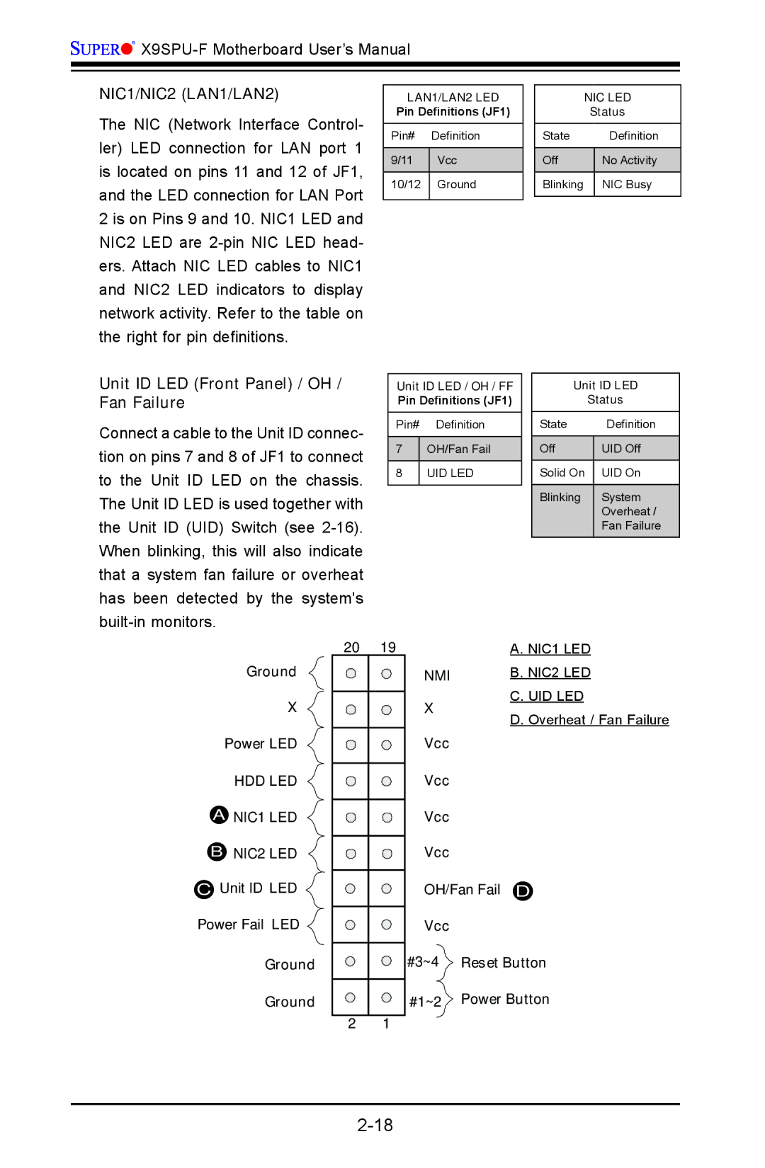
The NIC (Network Interface Control- ler) LED connection for LAN port 1 is located on pins 11 and 12 of JF1, and the LED connection for LAN Port 2 is on Pins 9 and 10. NIC1 LED and NIC2 LED are
Unit ID LED (Front Panel) / OH / Fan Failure
Connect a cable to the Unit ID connec- tion on pins 7 and 8 of JF1 to connect to the Unit ID LED on the chassis. The Unit ID LED is used together with the Unit ID (UID) Switch (see
LAN1/LAN2 LED
Pin Definitions (JF1)
Pin# Definition
9/11 | Vcc |
10/12 Ground
Unit ID LED / OH / FF
Pin Definitions (JF1)
Pin# Definition
7OH/Fan Fail
8UID LED
NIC LED
Status
State | Definition |
|
|
Off | No Activity |
|
|
Blinking | NIC Busy |
|
|
Unit ID LED
Status
State | Definition |
|
|
Off | UID Off |
|
|
Solid On | UID On |
|
|
Blinking | System |
| Overheat / |
| Fan Failure |
|
|
Ground
X
Power LED
HDD LED
ANIC1 LED
BNIC2 LED
CUnit ID LED ![]() Power Fail LED
Power Fail LED ![]()
Ground Ground
20 | 19 |
2 1
| A. NIC1 LED | |
NMI | B. NIC2 LED | |
X | C. UID LED | |
D. Overheat / Fan Failure | ||
| ||
Vcc |
| |
Vcc |
| |
Vcc |
| |
Vcc |
|
OH/Fan Fail D
Vcc
#3~4![]() Reset Button
Reset Button
#1~2 Power Button