X9SPU-F Motherboard User’s Manual
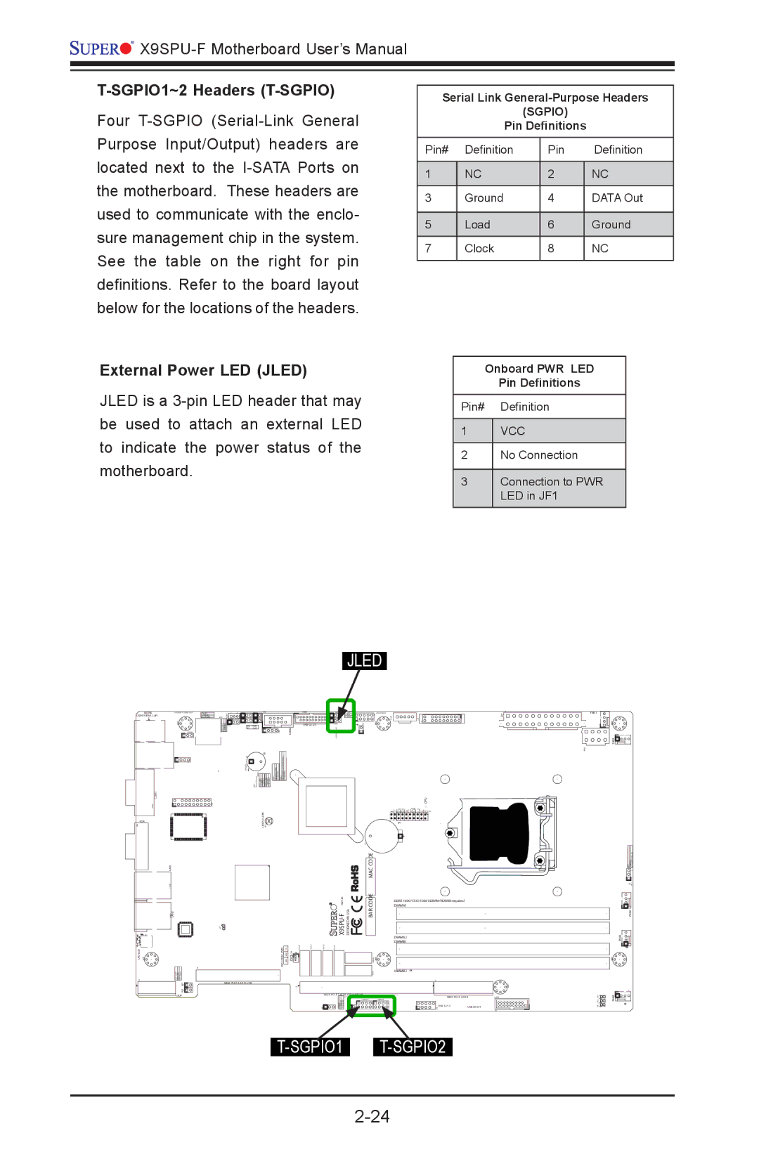
T-SGPIO1~2 Headers (T-SGPIO)
Four
Serial Link General-Purpose Headers
(SGPIO)
Pin Definitions
Pin# | Definition | Pin | Definition |
|
|
|
|
1 | NC | 2 | NC |
|
|
|
|
3 | Ground | 4 | DATA Out |
|
|
|
|
5 | Load | 6 | Ground |
|
|
|
|
7 | Clock | 8 | NC |
|
|
|
|
External Power LED (JLED)
JLED is a
Onboard PWR LED
Pin Definitions
Pin# Definition
1VCC
2No Connection
3Connection to PWR LED in JF1
| JLED |
|
| |
KB/MS |
|
|
|
|
USB4/5/IPMI_LAN |
|
|
|
|
|
|
|
| |
| COM2 |
|
|
|
| + |
|
|
|
COM1 |
|
| CPU |
|
VGA | CLEAR |
|
|
|
CMOS |
| JF1 |
| |
|
|
|
| |
|
|
| + |
|
LAN1 |
| MAC CODE |
|
|
| REV:1.00 | CODE | DIMMA1 |
|
|
|
| DDR3 1600/1333/1066 UDIMM/RDIMM required |
|
LAN2 | BAR | DIMMA2 |
| |
|
|
|
| |
|
|
| DIMMB1 |
|
JSD1:DOM PWR |
|
|
| |
|
|
| DIMMB2 |
|
| SBX2: |
|
|
|
UIOP | SBX1: |
| SBX3: | |
|
|
| USB 12/13 | USB |
T-SGPIO1 T-SGPIO2
FAN1
FAN2![]()
FAN3
FAN4![]()