Chapter 2: Installation
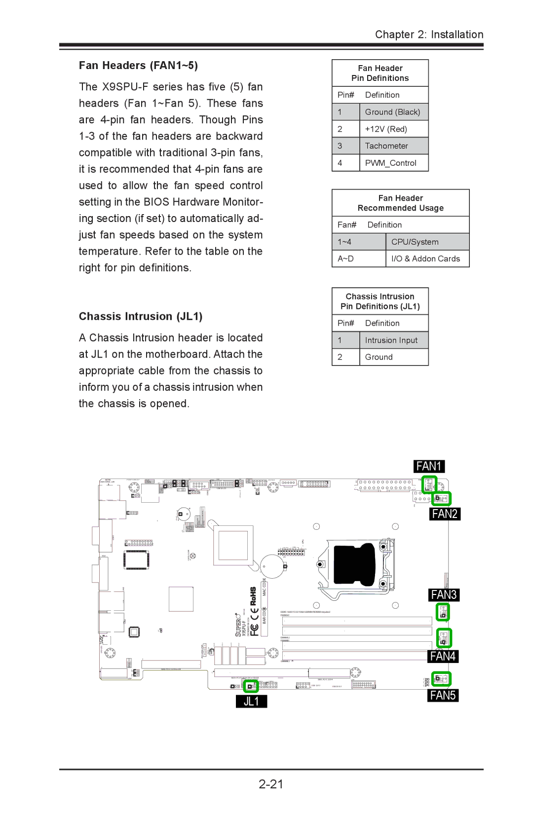
Fan Headers (FAN1~5)
The
Chassis Intrusion (JL1)
A Chassis Intrusion header is located at JL1 on the motherboard. Attach the appropriate cable from the chassis to inform you of a chassis intrusion when the chassis is opened.
Fan Header
Pin Definitions
Pin# |
| Definition | ||
|
|
|
|
|
1 |
| Ground (Black) | ||
|
|
|
|
|
2 |
| +12V (Red) | ||
|
|
|
|
|
3 |
| Tachometer | ||
|
|
|
|
|
4 |
| PWM_Control | ||
|
|
|
|
|
|
|
|
| |
|
| Fan Header | ||
| Recommended Usage | |||
Fan# |
| Definition | ||
|
|
|
| |
1~4 |
|
| CPU/System | |
|
|
|
| |
A~D |
|
| I/O & Addon Cards | |
|
|
|
|
|
Chassis Intrusion
Pin Definitions (JL1)
Pin# Definition
1Intrusion Input
2Ground
KB/MS |
|
|
USB4/5/IPMI_LAN |
|
|
|
| |
| COM2 |
|
| + |
|
COM1 |
|
|
VGA | CLEAR |
|
CMOS |
| |
|
| |
LAN1 |
| MAC CODE |
| REV:1.00 | CODE |
LAN2 | BAR | |
JSD1:DOM PWR |
| |
| SBX2: |
|
UIOP | SBX1: |
|
JL1
CPU
JF1
![]()
![]() +
+
DDR3 1600/1333/1066 UDIMM/RDIMM required
DIMMA1
DIMMA2
DIMMB1
DIMMB2
SBX3:
USB 12/13 | USB |
FAN1
FAN1
FAN2![]()
FAN2
FAN3
FAN3
FAN4![]()
FAN4
FAN5
FAN5