Chapter 2: Installation
Front Control Panel Pin Definitions
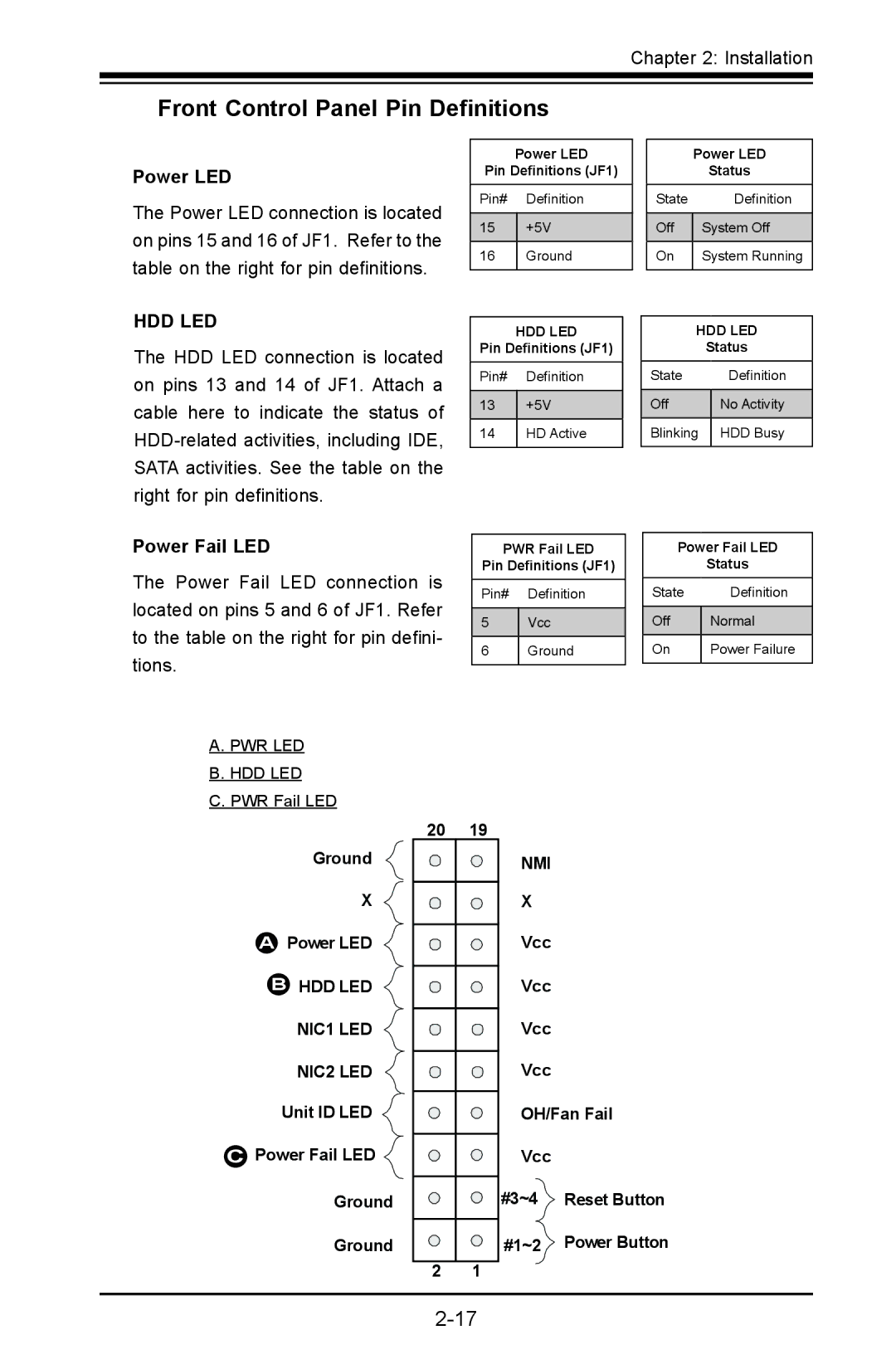
Power LED
The Power LED connection is located on pins 15 and 16 of JF1. Refer to the table on the right for pin definitions.
HDD LED
The HDD LED connection is located on pins 13 and 14 of JF1. Attach a cable here to indicate the status of
Power LED
Pin Definitions (JF1)
Pin# Definition
15+5V
16Ground
HDD LED
Pin Definitions (JF1)
Pin# Definition
13+5V
14HD Active
|
| Power LED | ||
|
|
| Status | |
|
|
|
|
|
| State |
| Definition | |
|
|
|
|
|
| Off |
| System Off | |
|
|
|
|
|
| On |
| System Running | |
|
|
|
| |
|
|
|
| |
|
| HDD LED | ||
|
|
| Status | |
| State |
| Definition | |
|
|
|
| |
| Off |
| No Activity | |
|
|
|
| |
| Blinking |
| HDD Busy | |
|
|
|
|
|
Power Fail LED
The Power Fail LED connection is located on pins 5 and 6 of JF1. Refer to the table on the right for pin defini- tions.
A. PWR LED
B. HDD LED
C. PWR Fail LED
PWR Fail LED
Pin Definitions (JF1)
Pin# Definition
5Vcc
6Ground
Power Fail LED
Status
State | Definition |
|
|
Off | Normal |
|
|
On | Power Failure |
|
|
Ground
X
APower LED
BHDD LED NIC1 LED
NIC2 LED
Unit ID LED
CPower Fail LED ![]() Ground
Ground
Ground
20 | 19 |
2 1
NMI
X
Vcc
Vcc
Vcc
Vcc
OH/Fan Fail
Vcc
#3~4![]() Reset Button
Reset Button
#1~2 Power Button