3 Installation | Model 3000PA | |
|
|
|
|
|
|
|
|
|
Figure 3-4: Analog Output Connections
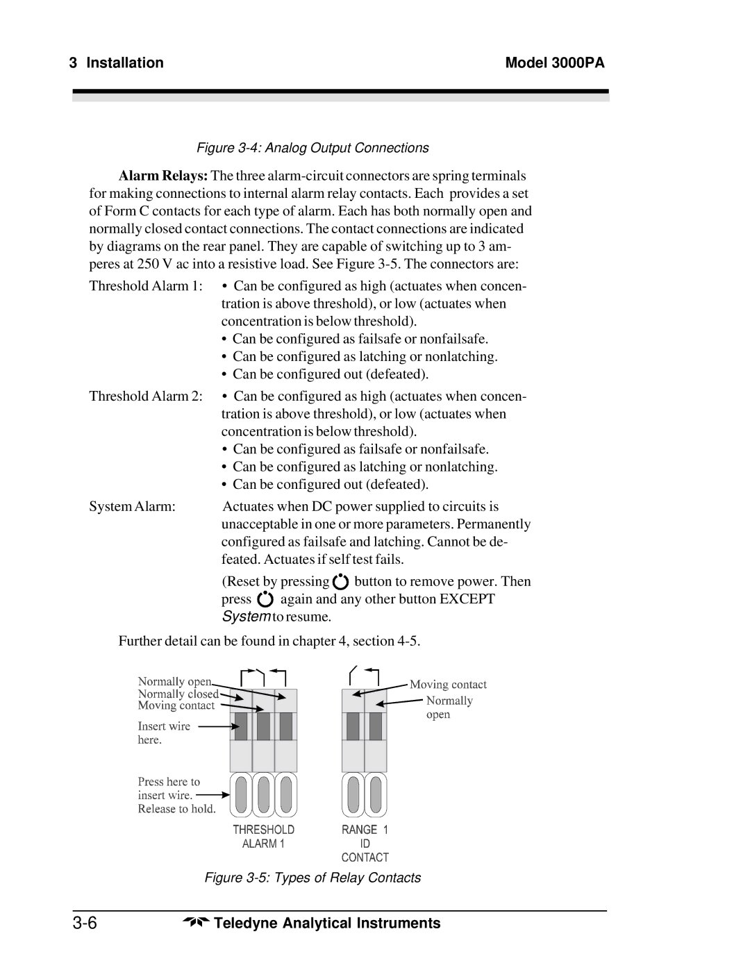
Alarm Relays: The three
Threshold Alarm 1: | • Can be configured as high (actuates when concen- | ||
| tration is above threshold), or low (actuates when | ||
| concentration is below threshold). | ||
| • Can be configured as failsafe or nonfailsafe. | ||
| • Can be configured as latching or nonlatching. | ||
| • Can be configured out (defeated). | ||
Threshold Alarm 2: | • Can be configured as high (actuates when concen- | ||
| tration is above threshold), or low (actuates when | ||
| concentration is below threshold). | ||
| • Can be configured as failsafe or nonfailsafe. | ||
| • Can be configured as latching or nonlatching. | ||
| • Can be configured out (defeated). | ||
System Alarm: | Actuates when DC power supplied to circuits is | ||
| unacceptable in one or more parameters. Permanently | ||
| configured as failsafe and latching. Cannot be de- | ||
| feated. Actuates if self test fails. | ||
| (Reset by pressing | button to remove power. Then | |
| press | again and any other button EXCEPT | |
System to resume.
Further detail can be found in chapter 4, section
| Figure |
|
|
Teledyne Analytical Instruments |