Percent Oxygen Analyzer | Operational Theory 2 | |
|
|
|
|
|
|
|
|
|
mizes residual gas pockets that can interfere with very low level oxygen analysis.
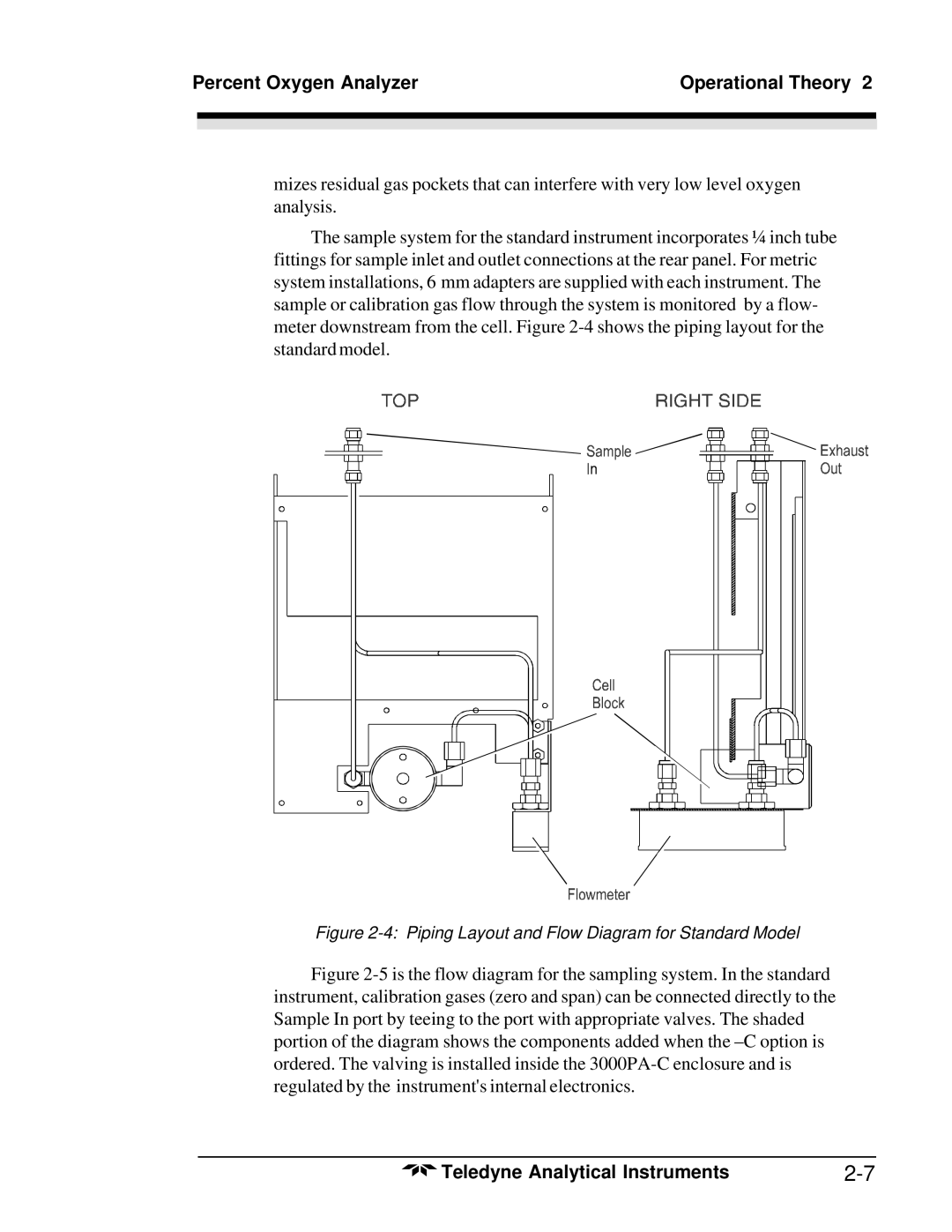
The sample system for the standard instrument incorporates ¼ inch tube fittings for sample inlet and outlet connections at the rear panel. For metric system installations, 6 mm adapters are supplied with each instrument. The sample or calibration gas flow through the system is monitored by a flow- meter downstream from the cell. Figure
Figure 2-4: Piping Layout and Flow Diagram for Standard Model
Figure 2-5 is the flow diagram for the sampling system. In the standard instrument, calibration gases (zero and span) can be connected directly to the Sample In port by teeing to the port with appropriate valves. The shaded portion of the diagram shows the components added when the –C option is ordered. The valving is installed inside the 3000PA-C enclosure and is regulated by the instrument's internal electronics.
Teledyne Analytical Instruments |