Installation | BDS 3960 | |
|
|
|
|
|
|
3.3Rear Panel Connections
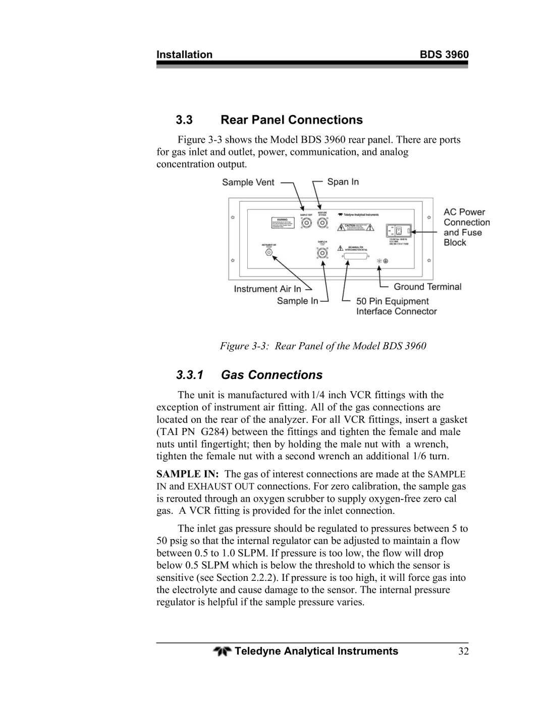
Figure 3-3 shows the Model BDS 3960 rear panel. There are ports for gas inlet and outlet, power, communication, and analog concentration output.
Figure 3-3: Rear Panel of the Model BDS 3960
3.3.1Gas Connections
The unit is manufactured with 1/4 inch VCR fittings with the exception of instrument air fitting. All of the gas connections are located on the rear of the analyzer. For all VCR fittings, insert a gasket (TAI PN G284) between the fittings and tighten the female and male nuts until fingertight; then by holding the male nut with a wrench, tighten the female nut with a second wrench an additional 1/6 turn.
SAMPLE IN: The gas of interest connections are made at the SAMPLE
IN andconnections. For zero calibration, the sample gas is rerouted through an oxygen scrubber to supply
The inlet gas pressure should be regulated to pressures between 5 to 50 psig so that the internal regulator can be adjusted to maintain a flow between 0.5 to 1.0 SLPM. If pressure is too low, the flow will drop below 0.5 SLPM which is below the threshold to which the sensor is sensitive (see Section 2.2.2). If pressure is too high, it will force gas into the electrolyte and cause damage to the sensor. The internal pressure regulator is helpful if the sample pressure varies.
Teledyne Analytical Instruments | 32 |