Handbook of Intercom Systems Engineering
Fine Print
Table of Contents
Design of Party-Line
Introduction to Matrix
Design of Wireless
Determining Intercom Needs
Page
Page
List of Figures
Wireless Intercom Interfaced to Matrix Intercom
Preface
Page
About the Authors
Page
Party-Line Systems
Introduction
Matrix Systems
Wireless Systems
Wireless Intercom Examples
Accessories
Example of Interfacing a TW System to a Matrix System
Matrix
Before We Begin
Tally
Rest Of The Book
Two-Wire
Some Definitions
Party-Line PL systems / Conference Line Intercom Systems
Short History
Brand Name Manufacturer
Present Day Systems and Manufacturers
System Components and Their Function
Belt Pack Headset User Station Functional Description
Speaker User Station Functional Description
Master Stations
Some Technical Notes About The Stations Above
How Each System Works
Four pin XLR
Five pin XLR
System Powering
Headset User Stations
Speaker User Stations
Outstanding Features of Each System
Cabling
Call Lights
Summary
Limitations of Each System
Some Definitions
Short History
How Each System Works
System Components and Their Function
Limitations of Each System
Outstanding Features of Each System
Audiocom intercom concept
RTS TW intercom concept
Overview
Defining And Meeting Your Needs
Application 1 Generic Single Channel Systems
Generic single channel Audiocom system
Audiocom Party-Line Intercom Equipment Listing #1
Generic single channel Clear-Comsystem
Clear-Com Party-Line Intercom Equipment Listing #1
RTS TW Party-Line Intercom Equipment Listing #1
Application 2 Two-Channel System TV, School, Cable
Clear-Com Party-Line Equipment Listing #2
Audiocom Party-Line Equipment Listing #2
RTS TW Party-Line Equipment Listing #2
Application 3 Theater System
Audiocom Party-Line Equipment Listing #3
Clear-Com Party-Line Equipment Listing #3
RTS TW Party-Line Equipment Listing #3
Audiocom
Application 4 Training Systems
Clear-Combased training intercom system
Clear-Com
RTS TW
Medium intercom system for television
Application 5 Medium System for Television
How an IFB Works
IFB System One Way Communications System
Studio and Some Field Applications
Field Application, Sports
Field Application, ENG Electronic News Gathering
Connecting Interfacing to Other Communications Systems
Interfacing Issues
Typical Interfacing Problem
Signal / Data Conversion
Level Problems
Modes
Call Light
Problems in Interfacing to Cameras
Interfacing Practice
Alternatives for Interfacing to Television Cameras
Headset Cable Lengths
Some Practical Considerations
Headphone Impedances
Wiring Practices/Workmanship Standards
Extended Range On Part Or All Of The System
Unbalanced vs. Balanced
Crosstalk Through a Common Circuit Ground
Cable Considerations
Crosstalk Through a Mutual Capacitance Of Two Conductors
Low Crosstalk Approach To Interconnection
Temperature Range Consideration
System Current/System Capacitances/Loading
Cooling Requirements
Magnetic Fields Hum Problems
Moisture / Contamination Protection
Defining and Meeting Your Needs
Connecting Interfacing to Other Communications Systems
IFB System One Way Communications System
Some Practical Considerations
Page
Page
Definitions
Introduction to Matrix Intercom Systems
KP-32 is a good example of an advanced user station keypanel
Example of Matrix Ports
History of Matrix Intercoms
X X X X X X
Number of Users Number of Crosspoints
Page
Page
Conventional Matrix vs. TDM Matrix
Modern Day Matrix Intercoms
Special Considerations
Configurability
Advantages
Size
Conference or PL described above
Ancillary Functions
Typical User Station Keypanel
More Complex Ancillary Functions
Page
Disadvantages
Cost
Complexity
You are in your kitchen QUICK, multiply 347.2 times
Page
Page
RTS Matrix Intercom Systems
Back-to-Basics
Typical Adam Matrix Connections
Let’s get started
To Begin
Studio a
Floor
Other
Control Room
Page
Page
RJ12 Modular Plug
Cable Considerations
Audio and Data Considerations
Polling Issues
Very Large Systems, Split Operation and Trunking
A Comparison of Relative System Sizes
Separate Studios, Separate Intercom
Fixed Trunking
Page
Independent Matrices in 2 Studios
Page
Cascaded Trunking
Interfacing
Signal Formats
TW and Matrix Signal Flows
Interconnecting Matrix, PL, and Wireless Systems
10 Wireless Intercom Interfaced to Matrix Intercom
+ +
12 TW to Matrix Interface
Software Considerations
Adam and Adam CS Basic Components
Adam
Page
History of Wireless Intercoms
Introduction to Wireless Intercoms
Page
First beltpack based wireless intercom system
Modern Day Wireless Intercoms
An example of a modern day wireless intercom system
Page
Ntsc Channel Configuration
Chan Start Video Chroma Audio
Chan Start Video Chroma Audio
Page
Page
Design of Wireless Intercom Systems
Field
An example of wireless transmission and reception
An example of reflected RF waves
Waves that are in phase combine to form a larger wave
Interference
An example of combining waves that are not 180 out of phase
2A B = C
+ C = D
3A 2B = C
Transmitters and Receivers
10 Transmitter block diagram
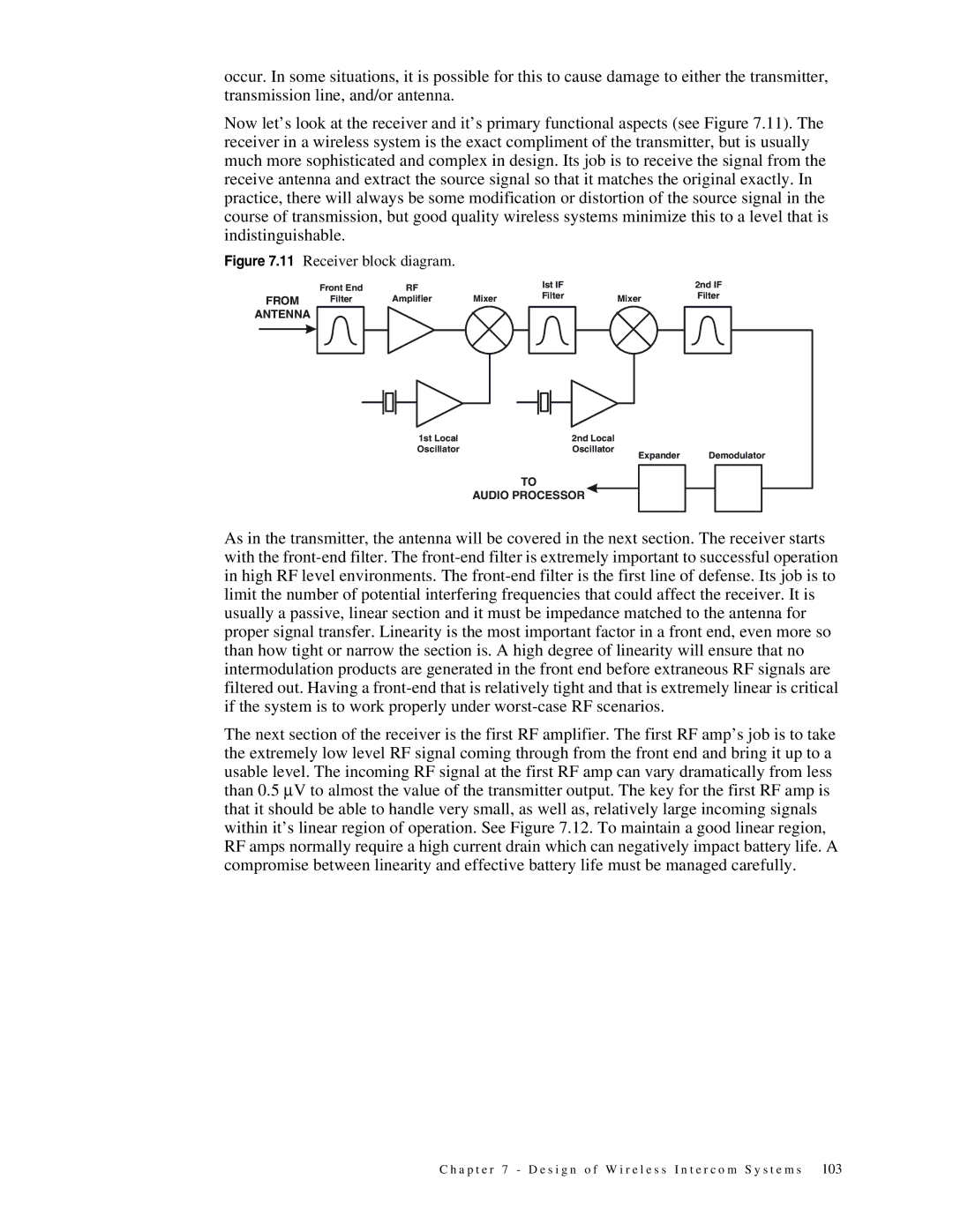
11 Receiver block diagram
12 Good linearity is a must for faithful signal reproduction
Antenna & Cable Considerations
Page
14 An example of a Yagi antenna
Page
Coaxial Cable Loss Chart
Installation
Page
Page
Page
Conference Versus Point-to-Point Requirements
Determining Intercom Needs
Page
General Overview
Fixed vs. Mobile Requirements
PS15 Power Supply/MCP2 Rack Kit
Determining Intercom Needs, two-wire, four-wire, or both?
Small Studio or ENG Vehicle
MCE325 Modular Programmable Station
Medium Sized Studio and Mobile Intercom
Headsets and Earsets not shown
TW5W Splitter
IFB325 Talent User Station
803-G1G5 Master Station
Two-wire Case Medium Intercom
BOP220 Connector Translation Assembly
PS31 Power Supply
System Interconnect
SAP1626 Source Assign Panel
Four-wire Case Medium Intercom
KP96-7 Keypanel
Zeus DSP2400 Matrix
TIF-2000 Intelligent Telco Interface
MKP4-K Modular Keypanel
PS15 Power Supply
IFB828 IFB Power Supply
SSA324 System-to-System Adapter
SAP612 Source Assign Panel
Large Studio or Mobile Vehicle
First Step--Determine the Size
Determining the Makeup of the Intercom Matrix
Users
IFB Circuits
Second Step--Determine the Panels
Cameras
Miscellaneous
Other Considerations in Determining Intercom Needs
How old is Too Old?
Maintenance
Expandability
Interoperability
Budget
Glossary
AWG
O s s a r y
CCU
CPS
Crosstalk Current Current Sources
DSP
EFP EIA
GND Gpio
Green Room Ground Ground Loop Potential
Ibew IFB
IR Drop Isolation
Light Signaling Limiter Line Line Level
Matrix Maximum SPL Mho Mic Micro µ Microcontroller
NAB Nabet NEC Nema
PLL
PZM
RFI RMS
Smpte
SPL
O s s a r y
Symbol for the unit of power, the watt
Index
IFB
ISO
STL
VHF