CY7C68033/CY7C68034
Figure 17 diagrams the timing relationship of the SLAVE FIFO signals during an asynchronous FIFO read. It shows a single read followed by a burst read.
•At t = 0 the FIFO address is stable and the SLCS signal is asserted.
•At t = 1, SLOE is asserted. This results in the data bus being driven. The data that is driven on to the bus is previous data, it data that was in the FIFO from a prior read cycle.
•At t = 2, SLRD is asserted. The SLRD must meet the minimum active pulse of tRDpwl and minimum
•The data that will be driven, after asserting SLRD, is the updated data from the FIFO. This data is valid after a propa- gation delay of tXFD from the activating edge of SLRD. In Figure 17, data N is the first valid data read from the FIFO. For data to appear on the data bus during the read cycle (that is SLRD is asserted), SLOE MUST be in an asserted state. SLRD and SLOE can also be tied together.
The same sequence of events is also shown for a burst read marked with T = 0 through 5. Note: In burst read mode, during SLOE is assertion, the data bus is in a driven state and outputs the previous data. Once SLRD is asserted, the data from the FIFO is driven on the data bus (SLOE must also be asserted) and then the FIFO pointer is incremented.
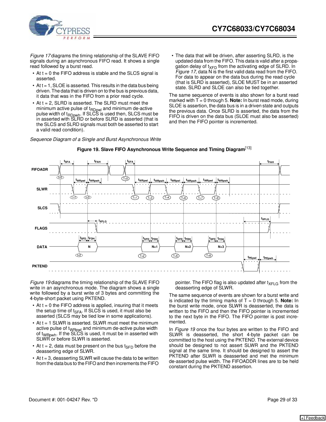
Sequence Diagram of a Single and Burst Asynchronous Write
Figure 19. Slave FIFO Asynchronous Write Sequence and Timing Diagram[13]
|
|
|
|
|
|
| tSFA |
| tFAH |
|
|
|
|
|
| tSFA |
|
|
|
|
|
|
|
|
|
|
|
| tFAH |
| |||||
|
|
|
|
|
|
|
|
|
|
|
|
|
|
|
|
|
|
|
|
|
| ||||||||||||||
|
|
|
|
|
|
|
|
|
|
|
|
|
|
|
|
|
|
|
|
|
|
|
|
|
|
|
|
|
|
|
|
|
|
|
|
FIFOADR |
|
|
|
|
|
|
|
|
|
|
|
|
|
|
|
|
|
|
|
|
|
|
|
|
|
|
|
|
| ||||||
|
|
|
|
|
|
|
|
|
|
|
|
|
|
|
|
|
|
|
|
|
|
|
|
|
|
|
|
|
|
|
|
|
|
| |
|
|
| t=0 |
|
| tWRpwl |
| tWRpwh |
|
|
|
|
|
| T=0 | tWRpwl |
| tWRpwh |
| tWRpwl |
| tWRpwh |
| tWRpwl tWRpwh |
| ||||||||||
|
|
|
|
|
|
|
|
|
|
|
|
|
|
|
|
|
|
|
|
| |||||||||||||||
|
|
|
|
|
|
|
|
|
|
|
|
|
|
|
|
|
|
|
|
|
|
|
| ||||||||||||
|
|
|
|
|
|
|
|
|
|
|
|
|
|
|
|
|
|
|
|
|
|
|
|
|
|
|
|
|
|
|
|
|
|
|
|
SLWR
t =1 | t=3 | T=1 | T=3 | T=4 | T=6 | T=7 | T=9 |
SLCS
|
|
|
|
|
|
|
| tXFLG |
|
|
|
|
|
|
|
|
|
|
|
|
|
|
|
|
|
| tXFLG |
|
|
|
| |||
FLAGS |
|
|
|
|
|
|
|
|
|
|
|
|
|
|
|
|
|
|
|
|
|
|
|
|
|
|
|
|
|
|
| |||
|
|
| tSFD | tFDH |
|
|
|
|
|
|
|
|
|
|
|
|
|
|
|
|
|
|
|
|
|
|
|
|
|
|
|
| ||
|
|
|
|
|
| t | t | FDH |
|
|
| t | t |
|
|
| t | t | FDH |
|
|
|
|
|
|
|
|
|
|
| ||||
|
|
|
|
|
|
|
|
|
|
|
|
|
|
|
|
|
|
|
|
|
|
| ||||||||||||
|
|
|
|
|
|
|
|
|
|
|
|
|
|
|
| |||||||||||||||||||
|
|
|
|
|
|
|
|
|
| SFD |
|
|
|
| SFD | FDH |
|
|
| SFD |
|
|
|
|
|
| ||||||||
DATA |
|
|
| N |
|
|
| N+1 |
|
|
|
| N+2 |
|
|
|
| N+3 |
|
|
|
|
| |||||||||||
|
|
|
|
|
|
|
|
|
|
|
|
|
|
|
|
|
|
| ||||||||||||||||
|
|
|
|
|
|
|
|
|
|
|
|
|
|
|
|
|
|
|
|
|
|
|
|
|
|
|
|
|
|
|
|
| ||
| t=2 |
|
|
|
| T=2 |
|
|
| T=5 |
|
| T=8 |
|
|
|
|
| tPEpwl tPEpwh | |||||||||||||||
|
|
|
|
|
|
|
|
|
|
|
|
|
|
|
|
|
|
|
|
|
|
|
|
|
|
| ||||||||
|
|
|
|
|
|
|
|
|
|
|
|
|
|
|
|
|
|
|
|
|
|
|
|
|
|
|
|
|
|
|
|
|
|
|
PKTEND
Figure 19 diagrams the timing relationship of the SLAVE FIFO write in an asynchronous mode. The diagram shows a single write followed by a burst write of 3 bytes and committing the 4-byte-short packet using PKTEND.
•At t = 0 the FIFO address is applied, insuring that it meets the setup time of tSFA. If SLCS is used, it must also be asserted (SLCS may be tied low in some applications).
•At t = 1 SLWR is asserted. SLWR must meet the minimum active pulse of tWRpwl and minimum
•At t = 2, data must be present on the bus tSFD before the deasserting edge of SLWR.
•At t = 3, deasserting SLWR will cause the data to be written from the data bus to the FIFO and then increments the FIFO
pointer. The FIFO flag is also updated after tXFLG from the deasserting edge of SLWR.
The same sequence of events are shown for a burst write and is indicated by the timing marks of T = 0 through 5. Note: In the burst write mode, once SLWR is deasserted, the data is written to the FIFO and then the FIFO pointer is incremented to the next byte in the FIFO. The FIFO pointer is post incre- mented.
In Figure 19 once the four bytes are written to the FIFO and SLWR is deasserted, the short
Document #: | Page 29 of 33 |
[+] Feedback