CY7C68033/CY7C68034
Table 4. Individual FIFO/GPIF Interrupt Sources
Priority | INT4VEC Value | Source | Notes |
1 | 0x580 | EP2PF | Endpoint 2 Programmable Flag |
|
|
|
|
2 | 0x584 | EP4PF | Endpoint 4 Programmable Flag |
|
|
|
|
3 | 0x588 | EP6PF | Endpoint 6 Programmable Flag |
|
|
|
|
4 | 0x58C | EP8PF | Endpoint 8 Programmable Flag |
|
|
|
|
5 | 0x590 | EP2EF | Endpoint 2 Empty Flag |
|
|
|
|
6 | 0x594 | EP4EF | Endpoint 4 Empty Flag |
|
|
|
|
7 | 0x598 | EP6EF | Endpoint 6 Empty Flag |
|
|
|
|
8 | 0x59C | EP8EF | Endpoint 8 Empty Flag |
|
|
|
|
9 | 0x5A0 | EP2FF | Endpoint 2 Full Flag |
|
|
|
|
10 | 0x5A4 | EP4FF | Endpoint 4 Full Flag |
|
|
|
|
11 | 0x5A8 | EP6FF | Endpoint 6 Full Flag |
|
|
|
|
12 | 0x5AC | EP8FF | Endpoint 8 Full Flag |
|
|
|
|
13 | 0x5B0 | GPIFDONE | GPIF Operation Complete |
|
|
|
|
14 | 0x5B4 | GPIFWF | GPIF Waveform |
|
|
|
|
If Autovectoring is enabled (AV4EN = 1 in the
Reset and Wakeup
Reset Pin
The input pin RESET#, will reset the
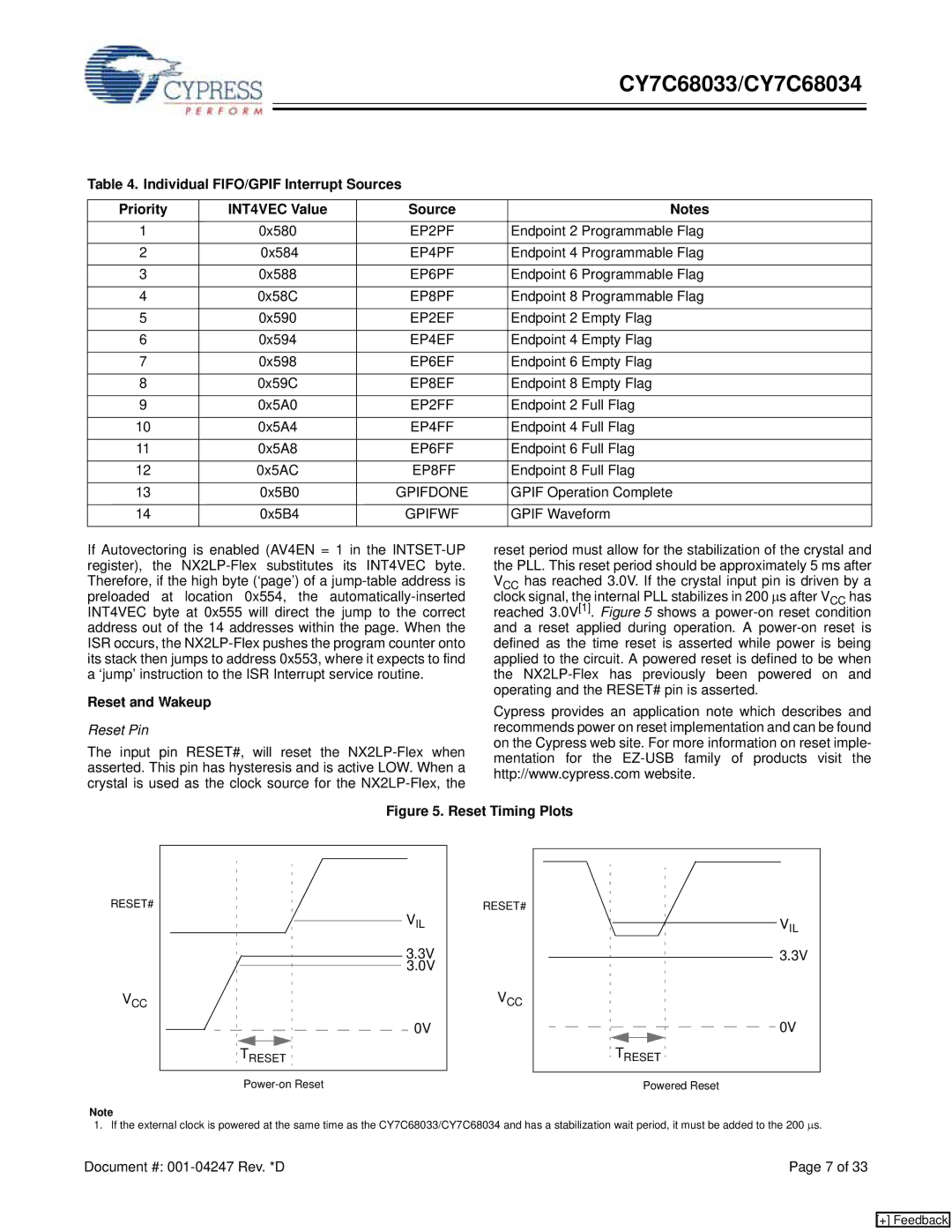
reset period must allow for the stabilization of the crystal and the PLL. This reset period should be approximately 5 ms after VCC has reached 3.0V. If the crystal input pin is driven by a clock signal, the internal PLL stabilizes in 200 μs after VCC has reached 3.0V[1]. Figure 5 shows a
Cypress provides an application note which describes and recommends power on reset implementation and can be found on the Cypress web site. For more information on reset imple- mentation for the
Figure 5. Reset Timing Plots
RESET#
VCC
|
|
|
|
|
|
|
|
|
|
|
|
|
|
|
|
|
|
|
|
|
|
|
|
|
| VIL | RESET# | ||||||||||||||||||||||||||||
|
|
|
|
|
|
|
|
|
|
|
|
|
|
|
|
|
|
|
|
|
|
|
|
|
|
|
|
|
|
|
|
|
|
|
|
|
|
|
|
|
|
|
|
|
|
|
|
|
|
|
|
| VIL | ||
|
|
|
|
|
|
|
|
|
|
|
|
|
|
|
|
|
|
|
|
|
|
|
|
|
|
|
|
|
|
|
|
|
|
|
|
|
|
|
|
|
|
|
|
|
|
|
|
|
|
|
|
| |||
|
|
|
|
|
|
|
|
|
|
|
|
|
|
|
|
|
|
|
|
|
|
|
|
|
|
|
|
|
|
|
|
|
|
|
|
|
|
|
|
|
|
|
|
|
|
|
|
|
|
|
| ||||
|
|
|
|
|
|
|
|
|
|
|
|
|
|
|
|
|
|
|
|
|
|
|
|
|
| 3.3V |
|
|
|
|
|
|
|
|
|
|
|
|
|
|
|
|
|
|
|
|
|
|
|
|
|
|
| 3.3V | |
|
|
|
|
|
|
|
|
|
|
|
|
|
|
|
|
|
|
|
|
|
|
|
|
|
|
|
|
|
|
|
|
|
|
|
|
|
|
|
|
|
|
|
|
|
|
|
|
|
|
|
|
| |||
|
|
|
|
|
|
|
|
|
|
|
|
|
|
|
|
|
|
|
|
|
|
|
|
|
| 3.0V | VCC | ||||||||||||||||||||||||||||
|
|
|
|
|
|
|
|
|
|
|
|
|
|
|
|
|
|
|
|
|
|
|
|
|
| ||||||||||||||||||||||||||||||
|
|
|
|
|
|
|
|
|
|
|
|
|
|
|
|
|
|
|
|
|
|
|
|
|
|
|
| ||||||||||||||||||||||||||||
|
|
|
|
|
|
|
|
|
|
|
|
|
|
|
|
|
|
|
|
|
|
|
|
|
|
| 0V |
|
|
|
|
|
|
|
|
|
|
|
|
|
|
|
|
|
|
|
|
|
|
|
|
|
|
| 0V |
|
|
|
|
|
|
|
|
|
|
|
|
|
|
|
|
|
|
|
|
|
|
|
|
|
|
|
|
|
|
|
|
|
|
|
|
|
|
|
|
|
|
|
|
|
|
|
|
|
|
|
|
|
| ||
|
|
|
|
|
|
|
|
|
|
|
|
|
|
|
|
|
|
|
|
|
|
|
|
|
|
| |||||||||||||||||||||||||||||
|
|
|
|
|
|
|
|
|
|
|
|
|
|
|
|
|
|
|
|
|
|
|
|
|
|
|
|
|
|
|
|
|
|
|
|
|
|
|
|
|
|
|
|
|
|
|
|
|
|
|
|
|
|
|
|
TRESET | TRESET |
| Powered Reset |
Note
1. If the external clock is powered at the same time as the CY7C68033/CY7C68034 and has a stabilization wait period, it must be added to the 200 μs.
Document #: | Page 7 of 33 |
[+] Feedback