CY7C68033/CY7C68034
Slave FIFO Asynchronous Read
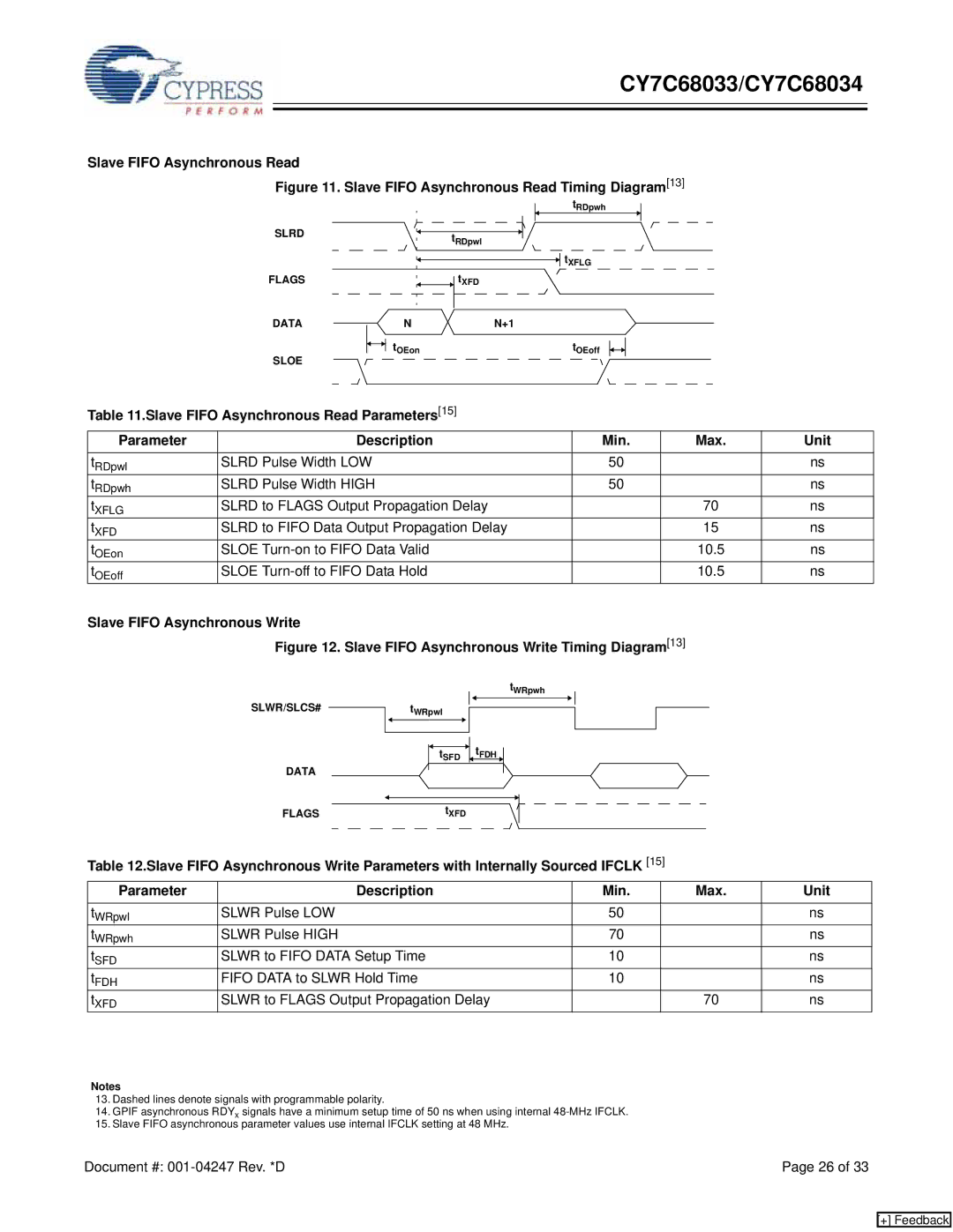
Figure 11. Slave FIFO Asynchronous Read Timing Diagram[13]
SLRD
FLAGS
DATA
SLOE
tRDpwh
tRDpwl
![]()
![]() tXFLG
tXFLG
![]() tXFD
tXFD
NN+1
|
|
|
|
| tOEon |
|
|
|
|
|
|
|
|
|
|
|
|
|
| tOEoff | |||||
|
|
|
|
|
|
|
|
|
|
|
|
|
|
|
|
|
|
| |||||||
|
|
|
|
|
|
|
|
|
|
|
|
|
|
|
|
|
|
| |||||||
|
|
|
|
|
|
|
|
|
|
|
|
|
|
|
|
|
|
|
|
|
|
|
|
|
|
Table 11.Slave FIFO Asynchronous Read Parameters[15]
Parameter | Description | Min. | Max. | Unit |
tRDpwl | SLRD Pulse Width LOW | 50 |
| ns |
tRDpwh | SLRD Pulse Width HIGH | 50 |
| ns |
tXFLG | SLRD to FLAGS Output Propagation Delay |
| 70 | ns |
tXFD | SLRD to FIFO Data Output Propagation Delay |
| 15 | ns |
tOEon | SLOE |
| 10.5 | ns |
tOEoff | SLOE |
| 10.5 | ns |
Slave FIFO Asynchronous Write
Figure 12. Slave FIFO Asynchronous Write Timing Diagram[13]
SLWR/SLCS#
DATA
tWRpwh
tWRpwl |
tSFD | tFDH |
FLAGStXFD
Table 12.Slave FIFO Asynchronous Write Parameters with Internally Sourced IFCLK [15]
Parameter | Description | Min. | Max. | Unit |
tWRpwl | SLWR Pulse LOW | 50 |
| ns |
tWRpwh | SLWR Pulse HIGH | 70 |
| ns |
tSFD | SLWR to FIFO DATA Setup Time | 10 |
| ns |
tFDH | FIFO DATA to SLWR Hold Time | 10 |
| ns |
tXFD | SLWR to FLAGS Output Propagation Delay |
| 70 | ns |
Notes
13.Dashed lines denote signals with programmable polarity.
14.GPIF asynchronous RDYx signals have a minimum setup time of 50 ns when using internal
15.Slave FIFO asynchronous parameter values use internal IFCLK setting at 48 MHz.
Document #: | Page 26 of 33 |
[+] Feedback