CY7C68033/CY7C68034
Endpoint RAM
Size
• 3 × 64 bytes (Endpoints 0 and 1)
• 8 × 512 bytes (Endpoints 2, 4, 6, 8)
Organization
•EP0
—Bidirectional endpoint zero,
•EP1IN, EP1OUT
—
•EP2,4,6,8
—Eight
—EP4 and EP8 can be double buffered, while EP2 and 6 can be either double, triple, or quad buffered.
For
Setup Data Buffer
A separate
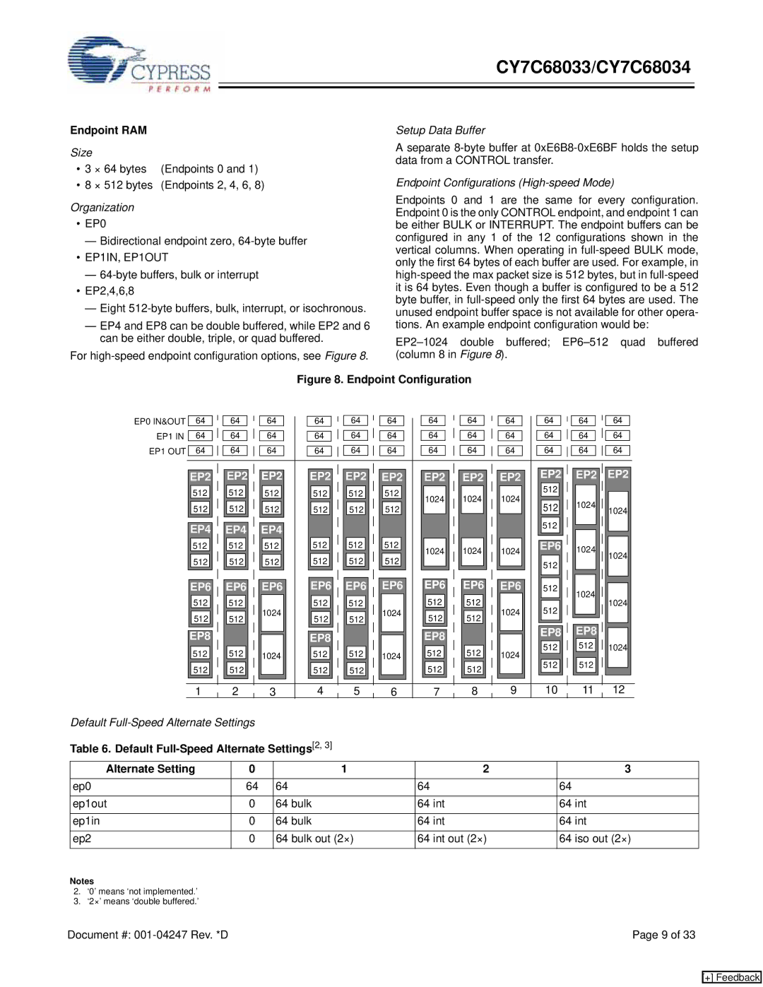
Endpoint Configurations (High-speed Mode)
Endpoints 0 and 1 are the same for every configuration. Endpoint 0 is the only CONTROL endpoint, and endpoint 1 can be either BULK or INTERRUPT. The endpoint buffers can be configured in any 1 of the 12 configurations shown in the vertical columns. When operating in
Figure 8. Endpoint Configuration
EP0 IN&OUT EP1 IN EP1 OUT
64 |
|
| 64 |
|
| 64 |
| 64 |
|
|
| 64 |
|
|
| 64 |
|
| 64 |
|
|
|
| 64 |
|
|
|
| 64 |
|
| 64 |
|
|
| 64 |
|
|
| 64 |
|
|
|
|
|
|
|
|
|
|
|
|
|
|
|
|
|
|
|
|
|
|
|
|
|
|
|
|
| ||||||||||||
64 |
|
| 64 |
|
| 64 |
| 64 |
|
| 64 |
|
| 64 |
|
| 64 |
|
|
| 64 |
|
|
| 64 |
|
| 64 |
|
|
| 64 |
|
|
| 64 | ||||
|
|
|
|
|
|
|
|
|
|
|
|
|
|
|
|
|
|
|
|
|
|
|
|
|
|
|
|
|
|
|
|
|
|
|
|
| ||||
64 |
|
| 64 |
|
| 64 |
| 64 |
|
|
| 64 |
|
|
| 64 |
|
| 64 |
|
|
|
| 64 |
|
|
|
| 64 |
|
| 64 |
|
|
| 64 |
|
|
| 64 |
|
|
|
|
|
|
|
|
|
|
|
|
|
|
|
|
|
|
|
|
|
|
|
|
|
|
|
|
|
|
|
|
|
|
|
|
|
|
|
|
|
|
|
|
|
|
|
|
|
|
|
|
|
|
|
|
|
|
|
|
|
|
|
|
|
|
|
|
|
|
|
|
|
|
|
|
|
|
|
|
|
|
EP2 |
|
| EP2 |
|
| EP2 |
| EP2 |
|
|
| EP2 |
|
|
| EP2 |
| EP2 |
|
|
| EP2 |
|
|
| EP2 |
| EP2 |
|
| EP2 |
|
| EP2 | ||||||
512 | 512 | 512 | 512 | 512 | 512 | 1024 | 1024 | 1024 | 512 |
|
|
|
|
| |||||||||
512 | 512 | 512 | 512 | 512 | 512 | 512 | 1024 |
| |||
|
|
| 1024 | ||||||||
|
|
|
| ||||||||
EP4 | EP4 | EP4 |
|
|
|
|
|
| 512 |
|
|
|
|
|
|
|
|
|
|
| |||
512 | 512 | 512 | 512 | 512 | 512 | 1024 | 1024 | 1024 | EP6 | 1024 | 1024 |
512 | 512 | 512 | 512 | 512 | 512 |
|
|
| 512 |
| |
|
|
|
|
| |||||||
|
|
|
|
|
|
|
|
|
|
| |
EP6 | EP6 | EP6 | EP6 | EP6 | EP6 | EP6 | EP6 | EP6 | 512 | 1024 |
|
512 | 512 |
| 512 | 512 |
| 512 | 512 |
|
| 1024 | |
1024 | 1024 | 1024 | 512 | 1024 | |||||||
512 | 512 | 512 | 512 | 512 | 512 |
|
| ||||
|
|
| EP8 | EP8 |
| ||||||
EP8 |
|
| EP8 |
|
| EP8 |
|
| 1024 | ||
512 | 512 | 1024 | 512 | 512 | 1024 | 512 | 512 | 1024 | 512 | 512 | |
512 | 512 |
| |||||||||
512 | 512 |
| 512 | 512 |
| 512 | 512 |
|
| ||
|
|
|
|
|
| ||||||
1 | 2 | 3 | 4 | 5 | 6 | 7 | 8 | 9 | 10 | 11 | 12 |
Default
Table 6. Default Full-Speed Alternate Settings[2, 3]
Alternate Setting | 0 | 1 | 2 | 3 |
ep0 | 64 | 64 | 64 | 64 |
|
|
|
|
|
ep1out | 0 | 64 bulk | 64 int | 64 int |
|
|
|
|
|
ep1in | 0 | 64 bulk | 64 int | 64 int |
|
|
|
|
|
ep2 | 0 | 64 bulk out (2×) | 64 int out (2×) | 64 iso out (2×) |
|
|
|
|
|
Notes
2.‘0’ means ‘not implemented.’
3.‘2×’ means ‘double buffered.’
Document #: | Page 9 of 33 |
[+] Feedback