|
|
|
|
|
|
| CY7C68033/CY7C68034 |
|
|
|
|
|
|
| |
|
|
|
|
|
|
|
|
|
|
|
|
|
|
|
|
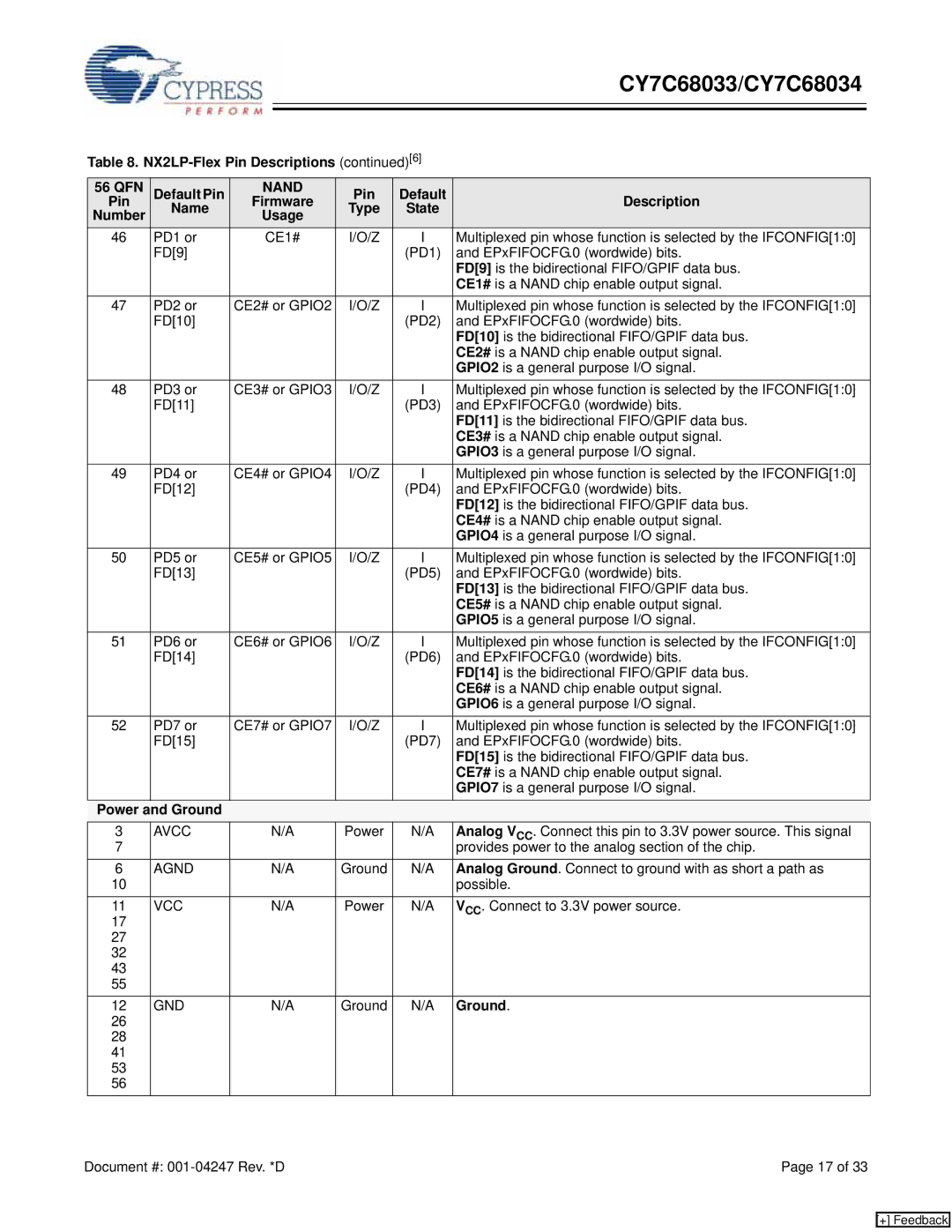
Table 8. |
| ||||||
56 QFN | Default Pin | NAND | Pin | Default | Description | ||
Pin | Name | Firmware | Type | State | |||
Number | Usage |
| |||||
|
|
|
| ||||
46 | PD1 or |
| CE1# | I/O/Z | I | Multiplexed pin whose function is selected by the IFCONFIG[1:0] | |
| FD[9] |
|
|
|
| (PD1) | and EPxFIFOCFG.0 (wordwide) bits. |
|
|
|
|
|
|
| FD[9] is the bidirectional FIFO/GPIF data bus. |
|
|
|
|
|
|
| CE1# is a NAND chip enable output signal. |
47 | PD2 or | CE2# or GPIO2 | I/O/Z | I | Multiplexed pin whose function is selected by the IFCONFIG[1:0] | ||
| FD[10] |
|
|
|
| (PD2) | and EPxFIFOCFG.0 (wordwide) bits. |
|
|
|
|
|
|
| FD[10] is the bidirectional FIFO/GPIF data bus. |
|
|
|
|
|
|
| CE2# is a NAND chip enable output signal. |
|
|
|
|
|
|
| GPIO2 is a general purpose I/O signal. |
48 | PD3 or | CE3# or GPIO3 | I/O/Z | I | Multiplexed pin whose function is selected by the IFCONFIG[1:0] | ||
| FD[11] |
|
|
|
| (PD3) | and EPxFIFOCFG.0 (wordwide) bits. |
|
|
|
|
|
|
| FD[11] is the bidirectional FIFO/GPIF data bus. |
|
|
|
|
|
|
| CE3# is a NAND chip enable output signal. |
|
|
|
|
|
|
| GPIO3 is a general purpose I/O signal. |
49 | PD4 or | CE4# or GPIO4 | I/O/Z | I | Multiplexed pin whose function is selected by the IFCONFIG[1:0] | ||
| FD[12] |
|
|
|
| (PD4) | and EPxFIFOCFG.0 (wordwide) bits. |
|
|
|
|
|
|
| FD[12] is the bidirectional FIFO/GPIF data bus. |
|
|
|
|
|
|
| CE4# is a NAND chip enable output signal. |
|
|
|
|
|
|
| GPIO4 is a general purpose I/O signal. |
50 | PD5 or | CE5# or GPIO5 | I/O/Z | I | Multiplexed pin whose function is selected by the IFCONFIG[1:0] | ||
| FD[13] |
|
|
|
| (PD5) | and EPxFIFOCFG.0 (wordwide) bits. |
|
|
|
|
|
|
| FD[13] is the bidirectional FIFO/GPIF data bus. |
|
|
|
|
|
|
| CE5# is a NAND chip enable output signal. |
|
|
|
|
|
|
| GPIO5 is a general purpose I/O signal. |
51 | PD6 or | CE6# or GPIO6 | I/O/Z | I | Multiplexed pin whose function is selected by the IFCONFIG[1:0] | ||
| FD[14] |
|
|
|
| (PD6) | and EPxFIFOCFG.0 (wordwide) bits. |
|
|
|
|
|
|
| FD[14] is the bidirectional FIFO/GPIF data bus. |
|
|
|
|
|
|
| CE6# is a NAND chip enable output signal. |
|
|
|
|
|
|
| GPIO6 is a general purpose I/O signal. |
52 | PD7 or | CE7# or GPIO7 | I/O/Z | I | Multiplexed pin whose function is selected by the IFCONFIG[1:0] | ||
| FD[15] |
|
|
|
| (PD7) | and EPxFIFOCFG.0 (wordwide) bits. |
|
|
|
|
|
|
| FD[15] is the bidirectional FIFO/GPIF data bus. |
|
|
|
|
|
|
| CE7# is a NAND chip enable output signal. |
|
|
|
|
|
|
| GPIO7 is a general purpose I/O signal. |
Power and Ground |
|
|
|
|
|
| |
3 | AVCC |
| N/A | Power | N/A | Analog VCC. Connect this pin to 3.3V power source. This signal | |
7 |
|
|
|
|
|
| provides power to the analog section of the chip. |
6 | AGND |
| N/A | Ground | N/A | Analog Ground. Connect to ground with as short a path as | |
10 |
|
|
|
|
|
| possible. |
11 | VCC |
| N/A | Power | N/A | VCC. Connect to 3.3V power source. | |
17 |
|
|
|
|
|
|
|
27 |
|
|
|
|
|
|
|
32 |
|
|
|
|
|
|
|
43 |
|
|
|
|
|
|
|
55 |
|
|
|
|
|
|
|
12 | GND |
| N/A | Ground | N/A | Ground. | |
26 |
|
|
|
|
|
|
|
28 |
|
|
|
|
|
|
|
41 |
|
|
|
|
|
|
|
53 |
|
|
|
|
|
|
|
56 |
|
|
|
|
|
|
|
Document #: | Page 17 of 33 |
[+] Feedback