OVERVIEW
Component Locations
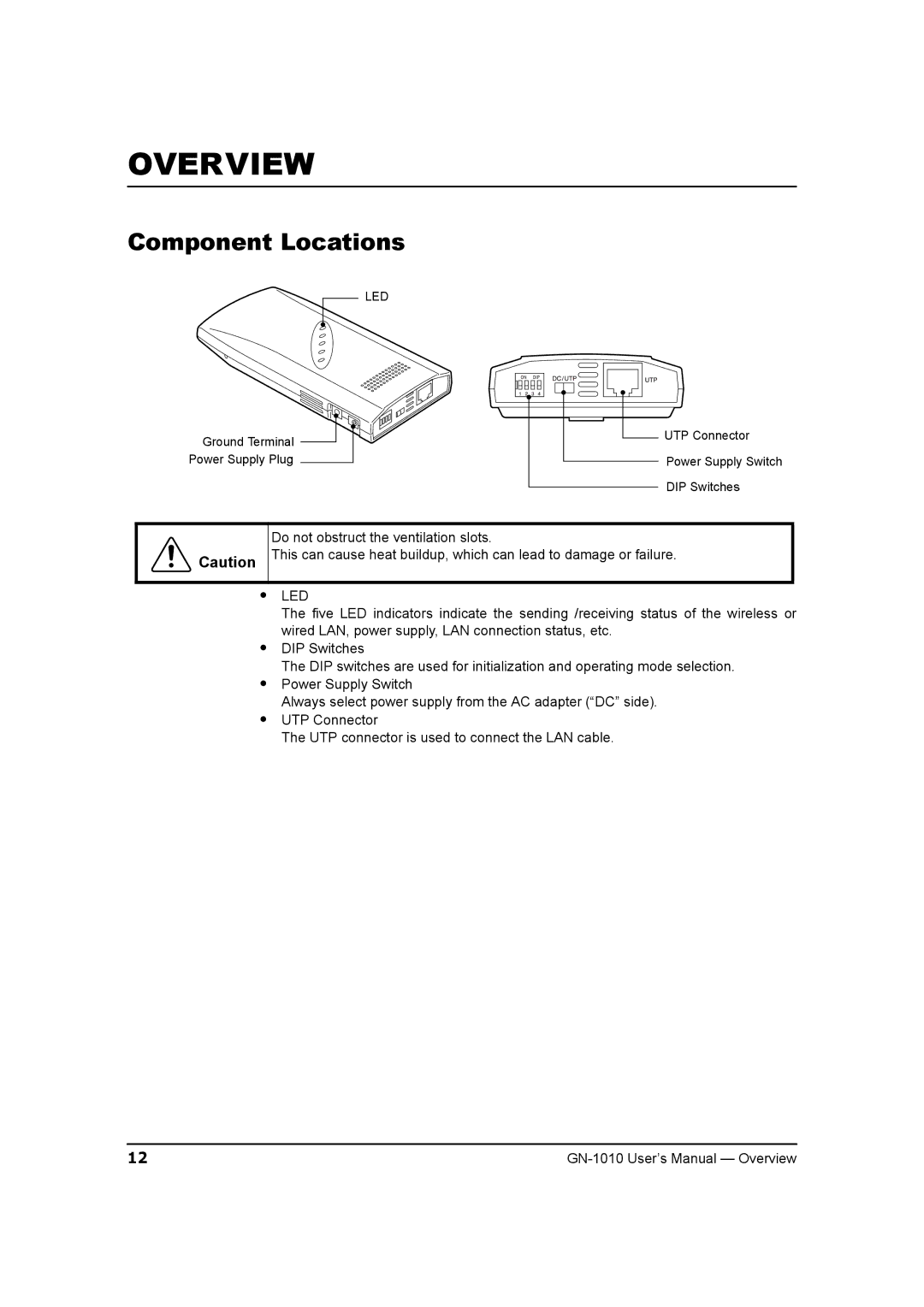
LED
Ground Terminal ![]()
Power Supply Plug
UTP Connector
Power Supply Switch
DIP Switches
Do not obstruct the ventilation slots.
Caution This can cause heat buildup, which can lead to damage or failure.
•LED
The five LED indicators indicate the sending /receiving status of the wireless or wired LAN, power supply, LAN connection status, etc.
•DIP Switches
The DIP switches are used for initialization and operating mode selection.
•Power Supply Switch
Always select power supply from the AC adapter (“DC” side).
•UTP Connector
The UTP connector is used to connect the LAN cable.
12 |