3. NAMES AND FUNCTIONS
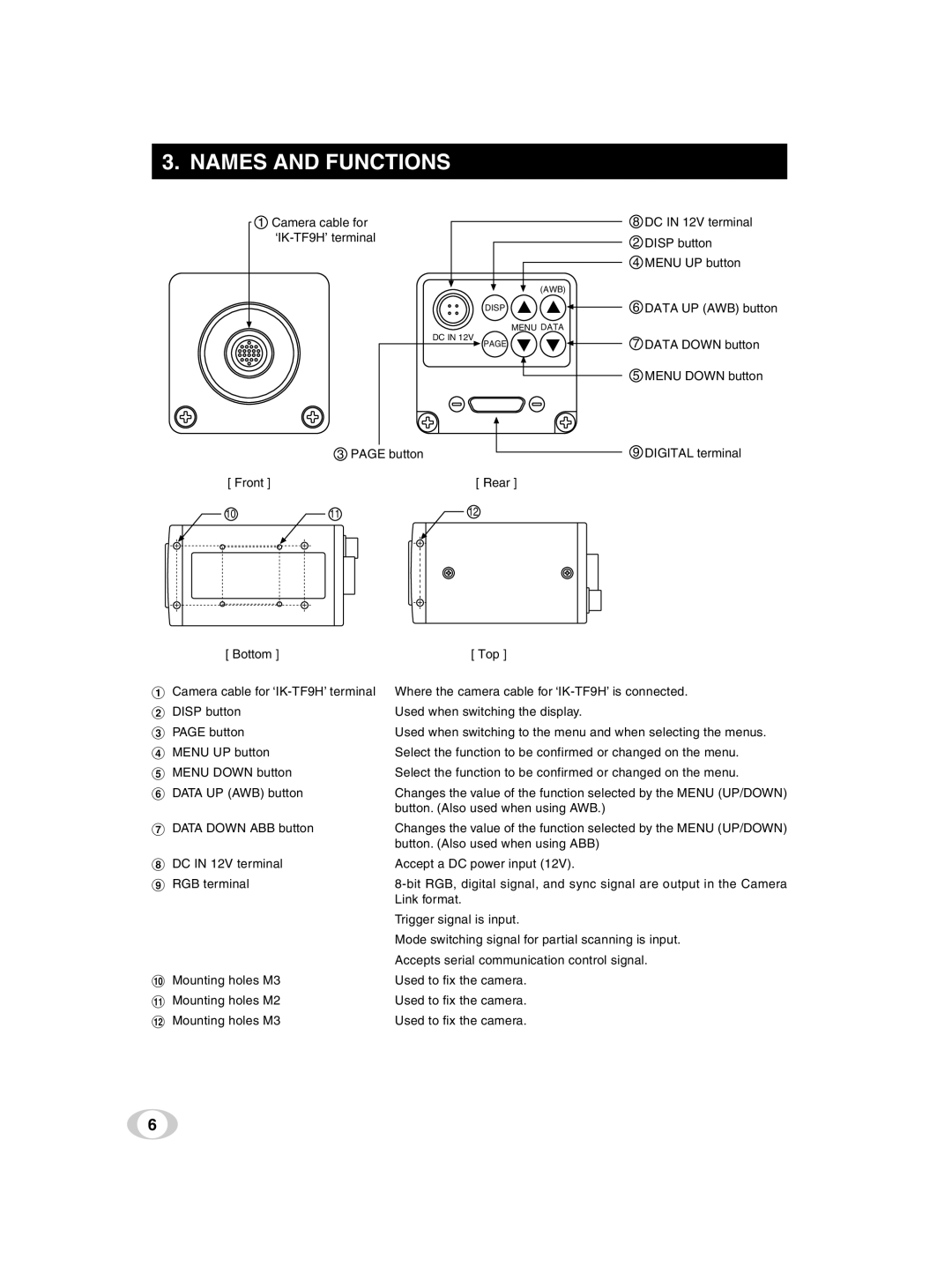
1Camera cable for
8 DC IN 12V terminal
2 DISP button
4 MENU UP button
(AWB)
|
| DISP | 6 | DATA UP (AWB) button |
|
| MENU DATA |
|
|
|
| DC IN 12V | 7 | DATA DOWN button |
|
| PAGE | ||
|
|
| 5 | MENU DOWN button |
| 3 PAGE button |
| 9 | DIGITAL terminal |
[ Front ] |
| [ Rear ] |
|
|
10 | 11 | 12 |
|
|
[ Bottom ] | [ Top ] |
1 Camera cable for | Where the camera cable for |
2 DISP button | Used when switching the display. |
3 PAGE button | Used when switching to the menu and when selecting the menus. |
4 MENU UP button | Select the function to be confirmed or changed on the menu. |
5 MENU DOWN button | Select the function to be confirmed or changed on the menu. |
6 DATA UP (AWB) button | Changes the value of the function selected by the MENU (UP/DOWN) |
| button. (Also used when using AWB.) |
7 DATA DOWN ABB button | Changes the value of the function selected by the MENU (UP/DOWN) |
| button. (Also used when using ABB) |
8 DC IN 12V terminal | Accept a DC power input (12V). |
9 RGB terminal | |
| Link format. |
| Trigger signal is input. |
| Mode switching signal for partial scanning is input. |
| Accepts serial communication control signal. |
! Mounting holes M3 | Used to fix the camera. |
" Mounting holes M2 | Used to fix the camera. |
# Mounting holes M3 | Used to fix the camera. |
6