Equium A300 Satego A300
Trademarks
Copyright
Disclaimer
Preface
Safety Precautions
Page
User input
Conventions
Acronyms
Keys Key operation
Table of Contents
LAN
Chapter Diagnostic Programs
Options
Chapter Replacement Procedures
HDD
CPU
Page
Appendices
Hardware Overview
Hardware Overview
Chapter Contents
Tables
Figures
Hardware Overview Features
Features
‰ ODD
‰ LAN BTO
Features Hardware Overview
Hardware Overview Features
Features Hardware Overview
ID Parts Description Placement
Computer Block Diagram
ODD
System Unit Components Hardware Overview
System Unit Components
Hardware Overview System Unit Components
− RTC − Gpio
Hardware Overview System Unit Components
System Unit Components Hardware Overview
2.5-inch HDD
Sata HDD HDD Specifications
DVD Super Multi +-R Double Layer
DVD-ROM mode CD-ROM mode
Hardware Overview Power Supply
Power Supply
5B1.6 Batteries Hardware Overview
Main Battery
Battery Charging Control
Batteries
Hardware Overview Batteries
RTC Battery
Troubleshooting
Chapter Troubleshooting
Chapter Contents
Procedure 2Connector Check Audio Test
HDD error code and status
Outline
Outline Troubleshooting
Troubleshooting Basic Flowchart
Basic Flowchart
Basic flowchart1/2
Basic Flowchart Troubleshooting
END
Basic Flowchart Troubleshooting
Procedure 1 Power Icon Check
Troubleshooting Power Supply
DC in LED
Power Supply Troubleshooting
Procedure 3 Replacement Check
Procedure 2 Connection Check
System Board
System Board Troubleshooting
Procedure 1 Message Check
Procedure 2 Test Program Check
Troubleshooting2.4 System Board
HDD
2.5-inch HDD Troubleshooting
Procedure 1 Message Check
Procedure 2 Partition Check
Procedure 3 Format Check
Troubleshooting 2.5-inch HDD
Code Status
Procedure 4 Test Program Check
Procedure 5 Connector Check and Replacement Check
Keyboard
Keyboard Troubleshooting
Procedure 1 Test Program Check
Procedure 2 Connector Check and Replacement Check
Procedure 3 Connector Check and Replacement Check
Troubleshooting Display
Procedure 1 External Monitor Check
Procedure 2 Test Program Check
Display Troubleshooting
ODD Optical Disk Drive
Troubleshooting ODD Drive
Procedure 1 ODD Cleaning Check
ODD Drive Troubleshooting
LAN
Finger PrintOptional
Procedure 2 Connector Check
Audio Test
Troubleshooting 10Audio Test
Ieee 1394 Test
Ieee 1394 Test Troubleshooting
Cooling Module
Troubleshooting 13Cooling Module
13Cooling Module Troubleshooting
Chapter Diagnostic Programs
Diagnostic Programs
Video Communication Comm
Page
General
General Diagnostic Programs
Diagnostic Programs General
Customization Test
Quick Start Diagnostic Programs
Quick Start
Quick Test
Diagnostic Programs Quick Start
CPU Speed Test Step by Step
Diagnostic Programs Quick Start
Keyboard Layout test
Audio Play Test
Hotkey Test
DMI Write
Audio Record Test
DMI Read
Diagnostic Programs Quick Start
System Information
View Logs
Test Running Status and Report Panel
Diagnostics Screen Explanation
Diagnostics Windows
Exit to Free DOS
Title Bar
‹ Program Name and Its Version Service Diagnostic Ver1.10
Quick Start Diagnostic Programs
Options Menu Notes
Diagnostic Programs 3Option
Options
Overview
Batch Parameters Configuration
Option Diagnostic Programs
Monitor Battery Life
Wait On Error
Break On Error
Pause Enable
Item’s Parameters Configuration
Load Batch Parameters
Parameters
Save Batch Parameters
LOG Parameters Setting
Specify LOG Viewer
Append to Old Log File
Log Device Info on Fail
Log file Name
Up, Page Down
LOG Viewer
↑, ↓
Ctrl+F3
Esc
Ctrl+Home
Ctrl+End
Pass
Subtests
Subtests Diagnostic Programs
HDD
Diagnostic Programs Subtests
Vesamem
Subtest 01 CPU
Diagnostic Programs System Test
System Test
NPU Interrupt Test
System Test Diagnostic Programs
NPU Basic Functions Test
Subtest 02 Boards
Subtest 03 FAN Speed Test
Diagnostic Programs System Test
Subtest 02 Parity
Memory Test Diagnostic Programs
Subtest 01 Bios ROM
Memory Test
Subtest 03 Patterns
Diagnostic Programs Memory Test
Subtest 04 Extended Pattern
Diagnostic Programs Memory Test
Subtest 08 Refresh Test
Subtest 05 Walking 1’s Test
Subtest 06 Walking 0’s Test
Subtest 07 Memory Address
Subtest 12 Memory Speed Test
Subtest 11 Data Bus Test
Subtest 01 HDD
Storage Diagnostic Programs
Password:hard disk
Storage
Diagnostic Programs Storage
Storage Diagnostic Programs
Subtest 02 ODD
Subtest
Peripheral Diagnostic Programs
Video
Diagnostic Programs Peripheral
Peripheral Diagnostic Programs
Subtest 02 640 * 480 VGA Mode
Subtest 04 Vesa Video Memory
Subtest 03 Vesa Video Modes
Subtest 06 LCD Panel Test
Subtest 05 AGP Test
Subtest 09 Direct Color Test
Subtest 08 Color Purity Test
Subtest 10 DAC/Palette Address
Peripheral Diagnostic Programs
Subtest 1394
Communication Comm
Subtest 01 LAN Card
Subtest Keyboard
Peripheral
Subtest Led Test
11Error Codes and Description Diagnostic Programs
Error Codes and description
03xx Board
Diagnostic Programs 11Error Codes and Description
FAN
31xx Audio
Can not find IEEE1394
Eject Error Wrong CD-ROM drive Exit from the wrong drive
Quick Test Item List
Quick Test Item List3 Diagnostic Programs
Chapter Replacement Procedures
Replacement Procedures
General
CPU
Replacement Procedures
Figures Removing the battery pack
33 Securing the CPU
HDD
General Replacement Procedures
Safety Precautions
Replacement Procedures General
Page
Before You Begin
Assembly Procedures
Disassembly Procedures
Screw Tightening Torque
Tools and Equipment
Colors of Screw Shanks
Symbols of Screws on the Computer Body
Symbol examples
Removing the battery pack
Removing the Battery Pack
Installing the Battery Pack
Removing the PC card
Removing the Optional PC Card
Installing the Optional PC Card
Removing the Memory Card
Installing the Memory Card
Removing the optional memory
Removing the Optional Memory
Installing the Optional Memory
Removing the HDD For Main HDD
HDD Replacement Procedures
Removing the HDD chassis
Replacement Procedures HDD
10 Removing the HDD pack
Removing the HDD For Second HDD
11 Removing the HDD chassis
Installing the HDD
Removing the ODD Bay Module
Replacement Procedures ODD Bay Module
ODD Bay Module
Installing the ODD Bay Module
ODD Bay Module Replacement Procedures
Assembling the ODD Drive
Disassembling the ODD Drive
Removing the Keyboard Cover and Keyboard
Keyboard Cover and Keyboard Replacement Procedures
Keyboard Cover and Keyboard
Replacement Procedures Keyboard Cover and Keyboard
Installing the Keyboard Cover and Keyboard
Removing the Wireless LAN Card
Wireless LAN Card
Replacement Procedures Wireless Lan Card
Installing the Wireless LAN Card
Wireless Lan Card Replacement Procedures
Removing the MDC Module
Replacement Procedures MDC Module
MDC Module
Installing the MDC Module
MDC Module Replacement Procedures
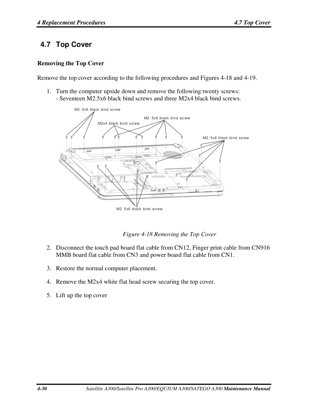
Removing the Top Cover
Replacement Procedures Top Cover
Top Cover
Installing the Top Cover
Top Cover Replacement Procedures
Removing the Speakers
Replacement Procedures Speakers
Installing the Speakers
Speakers
Removing the Audio cable
Audio Cable Replacement Procedures
Audio Cable
Installing the Audio cable
Replacement Procedures Audio Cable
Removing the Display Assembly
Display Assembly
Display Assembly Replacement Procedures
Installing the Display Assembly
Replacement Procedures Display Assembly
Removing the System Board, AC-IN cable, Fan and Robson card
System Board, AC-IN cable, Fan and Robson card
24 Removing the system board
Page
Removing the CPU Cooling Module and Fan for VGA card Model
Replacement Procedures CPU Cooling Module
CPU Cooling Module
Installing the CPU Cooling Module and Fan
CPU Cooling Module Replacement Procedures
Installing the CPU Cooling Module and Fan for VGA card Model
27 Removing the CPU cooling module
Removing the CPU Cooling Module
28 Applying silicon grease
Installing the CPU Cooling Module and Fan
Removing the CPU
Replacement Procedures 13 CPU
13 CPU
Installing the CPU
13 CPU Replacement Procedures
31 Securing the CPU
USB board, Bluetooth Card, FM card and Felica card
Page
Removing the Display Mask
Display Mask Replacement Procedures
Display Mask
34 Removing the display mask
Replacement Procedures Display Mask
Installing the Display Mask
Removing the FL Inverter Board
Replacement Procedures FL Inverter Board
FL Inverter Board
Installing the FL Inverter Board
FL Inverter Board Replacement Procedures
Removing the 15.1-inch LCD module
Replacement Procedures LCD Module
LCD Modules
LCD module
LCD Module Replacement Procedure s
Installing the 15.1-inch LCD Module
Removing the CCD Board and MIC
CCD Board and MIC Replacement Procedures
CCD Board and MIC
Installing the CCD Board and MIC
Replacement Procedures CCD Board and MIC
Page
Page
Page
Page
Appendices
CN1
JACK800
Apx. a Handling the LCD Module Appendices
Precautions for handling the LCD module
Appendices Apx. a Handling the LCD Module
Apx. a Handling the LCD Module Appendices
Appendices Apx. a Handling the LCD Module
Apx. a Handling the LCD Module Appendices
Apx. B Board Layout Appendices
Appendix B Board Layout System Board Front View
Figure B-2 Board layout back
Appendices Apx. B Board Layout
Appendix C C-3
Appendices Apx. C Pin Assignments
Head Phone with Spdif Connector 8-Pin
System Board
Table C-1 Power/B Connector pin assignments 4-Pin
Table C-2 Internal Speaker Connector pin assignments 6-Pin
Table C-3 Hot Key/B Connector pin assignments 6-Pin
Table C-6 LCD/Fl Inverter Connector pin assignments 40-Pin
Camera Connector 5-Pin
Table C-4 Camera Connector pin assignments 5-Pin
Table C-5 Hot Key /B Connector pin assignments 12-Pin
Table C-8 CRT Connector pin assignments 14-Pin
Modem Connector 12-Pin
Table C-7 Modem Connector pin assignments 12-Pin
Table C-9 Broadcom Connector pin assignments 52-Pin
Broadcom Connector 52-Pin
CN11
CN10 Mini Card Connector 52-Pin
Table C-10 Mini Card Connector pin assignments 52-Pin
CN13
CN12 Touch Pad Connector 6-Pin
Table C-12 Touch Pad Connector pin assignments 6-Pin
CN15
CN14 FingerPrint/B Connector 4-Pin
CN16 Felica Connector 6-Pin
CN17 Express Card Connector 26-Pin
CN800
CN18
CN19
CN803
CN802 FAN Connector 3-Pin
CN801
PEGCRXN5
Crtr LVDSTXDU0P
PEGCTXP12
Table C-24 DDR2 DIMM0 Socket pin assignments 200-Pin
CN804
MACAS#
ICH3SSMDATA
Table C-25 DDR2 DIMM1 Socket pin assignments 200-Pin
CN805
MBCAS#
135 MBDATA34 136 137 MBDATA35 138 139
CN809
CN808 Hdmi Connector 19-Pin
CN806
Table C-29 Robson Card Connector pin assignments 52-Pin
CN810 Robson Card Connector 52-Pin
CN813
CN811 USB Port#0 Connector 4-Pin
CN812 HDD#0 Connector 22-Pin
Table C-34 Card Reader Socket pin assignments 44-Pin
Table C-33 USB Port#1 Connector pin assignments 4-Pin
CN814
CN815
CN9061
CN816
CN9060
Table C-39 RJ45 Connector pin assignments 12-Pin
CN9062 Fmrl Connector 2-Pin
JACK801 Head Phone with Spdif Connector 8-Pin
Table C-38 Fmrl Connector pin assignments 2-Pin
Table C-41 Micro Phone Connector pin assignments 6-Pin
JACK802 Micro Phone Connector 6-Pin
Keyboard Scan/Character Codes Appendices
Appendix D Keyboard Scan/Character Codes
Table D-1 Scan codes set 1 and set 2 2/4
Appendices Keyboard Scan/Character Codes
Table D-1 Scan codes set 1 and set 2 3/4
Table D-1 Scan codes set 1 and set 2 4/4
Table D-2 Scan codes with left Shift key
Table D-3 Scan codes in Numlock mode
Table D-5 Scan codes in overlay mode
Table D-7 No.126 key scan code
Japan JP Keyboard
United States US Keyboard
Apx E Key Layout
Spanish SP Keyboard
Korean KR Keyboard
French FR Keyboard
Canadian Bilingual QB Keyboard
Italian IT Keyboard
German GR Keyboard
Apx E Key Layout Appendices
Taiwan TC Keyboard
Portuguese PT Keyboard
Arabic AR Keyboard
11 DU, UE, US International USE Keyboard
Russian RU Keyboard
Belgian be Keyboard
Swedish SW Keyboard
Swiss/Switzerland SL Keyboard
Danish DK Keyboard
Norwegian no Keyboard
Greek GK Keyboard
Turkey TR Keyboard
Herbrew HE Keyboard
Canadian Multinational CM Keyboard
Scandinavian N5 Keyboard
Czech CZ Keyboard
Slovakian SK Keyboard
Hungary HU Keyboard
Thai TH Keyboard
Yugoslavia YU Keyboard
Turkish F TF Keyboard
United Kingdom EN Keyboard
Tools
Apx. F Bios Rewrite Procedures Appendices
Rewriting the Bios
Rewriting the EC/KBC
Apx. G EC/KBC Rewrite Procedures Appendices
Tools