Projector exterior view
Front / Upper side
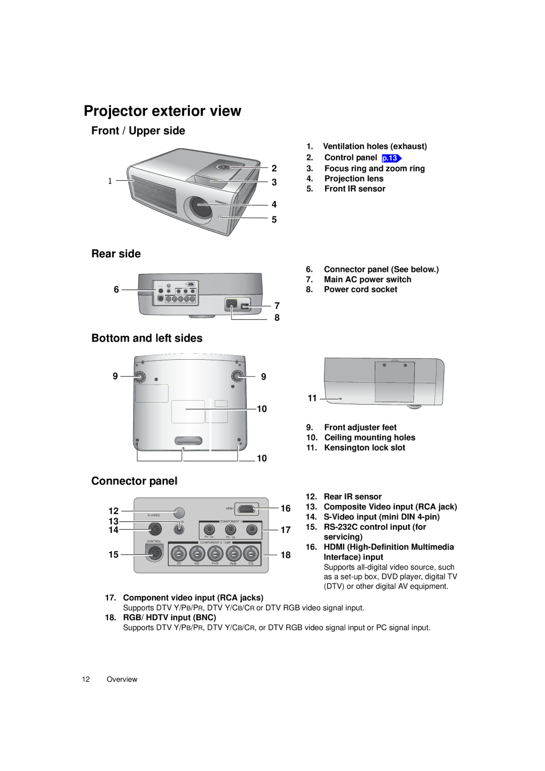
1. Ventilation holes (exhaust)
2. Control panel p.13
![]()
![]() 2 3. Focus ring and zoom ring
2 3. Focus ring and zoom ring
1 ![]()
![]()
![]() 3 4. Projection lens
3 4. Projection lens
5. Front IR sensor
![]()
![]() 4
4 ![]() 5
5
Rear side
6
VIDEO
CONTROL
VD
|
| HDM1 |
|
|
| COMPONENT 1 |
|
P | / C | P / C |
|
COMPONENT 2 / GBR |
| ||
HD | P /R | P /B | Y/G |
6.Connector panel (See below.)
7.Main AC power switch
8.Power cord socket
7
8
Bottom and left sides
9 | 9 |
10 |
10 |
11
9.Front adjuster feet
10.Ceiling mounting holes
11.Kensington lock slot
Connector panel
12 | HDM1 | |
13 | VIDEO | COMPONENT 1 |
14 |
|
|
PR / CR PB / CB
CONTROL | COMPONENT 2 / GBR |
15
VD HD PR/R PB/B Y/G
12. Rear IR sensor
1613. Composite Video input (RCA jack)
14.
1715.
16.HDMI
18Interface) input
Supports
17.Component video input (RCA jacks)
Supports DTV Y/PB/PR, DTV Y/CB/CR or DTV RGB video signal input.
18.RGB/ HDTV input (BNC)
Supports DTV Y/PB/PR, DTV Y/CB/CR, or DTV RGB video signal input or PC signal input.
12 Overview