Unit Operation
24 VAC |
|
| Compr 2 |
|
|
|
| ||
|
|
|
|
|
|
| |||
HPC | LPC | Compr 1 |
|
|
|
|
| ||
|
|
|
|
|
|
| |||
|
| Binary Outputs |
|
|
|
| |||
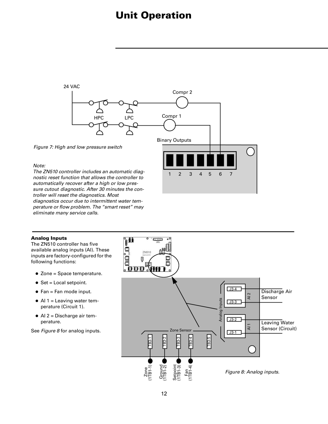
Figure 7: High and low pressure switch |
|
|
|
|
|
|
|
| |
Note: |
|
|
|
|
|
|
|
| |
The ZN510 controller includes an automatic diag- | 1 | 2 | 3 | 4 | 5 | 6 | 7 | ||
nostic reset function that allows the controller to | |||||||||
|
|
|
|
|
|
| |||
automatically recover after a high or low pres- |
|
|
|
|
|
|
| ||
sure cutout diagnostic. After 30 minutes the con- |
|
|
|
|
|
|
| ||
troller will reset the diagnostics. Most |
|
|
|
|
|
|
|
| |
diagnostics occur due to intermittent water tem- |
|
|
|
|
|
|
| ||
perature or flow problem. The “smart reset” may |
|
|
|
|
|
|
| ||
eliminate many service calls. |
|
|
|
|
|
|
|
| |
Analog Inputs
The ZN510 controller has five available analog inputs (AI). These inputs are
zZone = Space temperature.
zSet = Local setpoint.
zFan = Fan mode input.
zAI 1 = Leaving water tem- perature (Circuit 1).
zAI 2 = Discharge air tem- perature.
See Figure 8 for analog inputs.
Zone Sensor
| ||||
|
|
|
|
|
|
|
|
|
|
|
|
|
|
|
Analog Inputs
AI 2
AI 1
Discharge Air Sensor
Leaving Water Sensor (Circuit)
Zone | Ground | Setpoint | Fan |
|
|
| Figure 8: Analog inputs. |
12
