Heating or Cooling Control Mode Operation
Heating or Cooling
Operation
For both single and dual compressor operation, the ZN510 controller cycles the compressor(s) on and off to meet heating or cooling zone demands. The controller uses the
unit capacity and pulse width modulation (PWM) logic along with minimum on/off timers to determine the operation for compressor 1.
With a dual compressor unit, if the desired conditions are not met by
controlling only the first compressor, the controller runs compressor 1 continuously and controls compressor 2 according to PWM logic along with the minimum on/off timers. See Table 6 for heat pump heating or cooling operation.
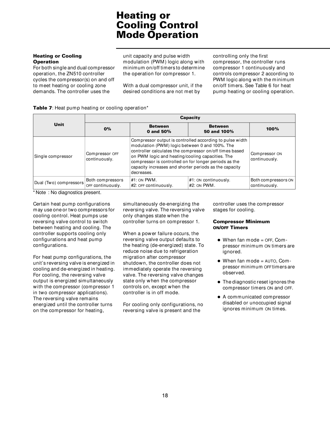
Table 7: Heat pump heating or cooling operation*
|
|
| Capacity |
| ||
Unit |
|
|
|
|
| |
0% | Between |
| Between | 100% | ||
|
| |||||
| 0 and 50% |
| 50 and 100% | |||
|
|
|
| |||
|
|
|
|
| ||
|
| Compressor output is controlled according to pulse width |
| |||
|
| modulation (PWM) logic between 0 and 100%. The |
| |||
| Compressor OFF | controller calculates the compressor on/off times based | Compressor ON | |||
Single compressor | on PWM logic and heating/cooling capacities. The | |||||
continuously. | continuously. | |||||
| compressor is controlled on for longer periods as the | |||||
|
|
| ||||
|
| capacity increases and shorter periods as the capacity |
| |||
|
| decreases. |
|
|
| |
|
|
|
|
|
| |
Dual (Two) compressors | Both compressors | #1: ON PWM. |
| #1: ON continuously. | Both compressors ON | |
| OFF continuously. | #2: OFF continuously. |
| #2: ON PWM. | continuously. | |
*Note: No diagnostics present.
Certain heat pump configurations may use one or two compressors for cooling control. Heat pumps use reversing valve control to switch between heating and cooling. The controller supports cooling only configurations and heat pump configurations.
For heat pump configurations, the unit’s reversing valve is energized in cooling and
simultaneously
When a power failure occurs, the reversing valve output defaults to the heating
For cooling only configurations, no reversing valve is present and the
controller uses the compressor stages for cooling.
Compressor Minimum
ON/OFF Timers
zWhen fan mode = OFF, Com- pressor minimum ON timers are ignored.
zWhen fan mode = AUTO, Com- pressor minimum OFF timers are observed.
zThe diagnostic reset ignores the compressor timers ON and OFF.
zA communicated compressor disabled or unoccupied signal ignores minimum ON times.
18