Unit Operation
Low Temperature Detection The low temperature detection diagnostic protects the heat exchanger by using an analog leaving water temperature sensor to protect refrigerant circuit 1 and a binary low temperature detection device to protect refrigerant circuit
2.Each individual refrigerant circuit is disabled when the low
temperature condition exists for that circuit.
For two compressor units, the controller responds to low temperature detection by allowing the fan to operate, while disabling the compressor for the faulty circuit. The compressor for the normal circuit continues to operate. The
outdoor air damper also operates normally.
All unit operation is disabled when the heat pump shuts down both circuits, due to low temperature conditions. See Table 3 for more information.
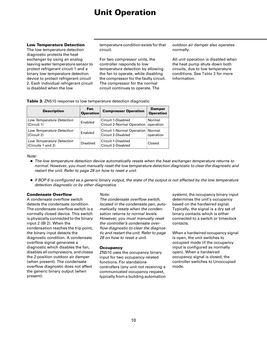
Table 3: ZN510 response to low temperature detection diagnostic
Description | Fan | Compressor Operation | Damper | |
Operation | Operation | |||
|
|
|
| |
Low Temperature Detection | Enabled | Circuit | Normal | |
(Circuit 1) | Circuit | operation | ||
| ||||
|
|
|
| |
Low Temperature Detection | Enabled | Circuit | Normal | |
(Circuit 2) | Circuit | operation | ||
| ||||
|
|
|
| |
Low Temperature Detection | Disabled | Circuit | Closed | |
(Circuits 1 and 2) | Circuit | |||
|
| |||
|
|
|
|
Note:
zThe low temperature detection device automatically resets when the heat exchanger temperature returns to normal. However, you must manually reset the low temperature detection diagnostic to clear the diagnostic and restart the unit. Refer to page 28 on how to reset a unit.
zIf BOP 6 is configured as a generic binary output, the state of the output is not affected by the low temperature detection diagnostic or by other diagnostics.
Condensate Overflow
A condensate overflow switch detects the condensate condition. The condensate overflow switch is a normally closed device. This switch is physically connected to the binary input 2 (BI 2). When the condensation reaches the trip point, the binary input detects the diagnostic condition. A condensate overflow signal generates a diagnostic which disables the fan, disables all compressors, and closes the
Note:
The condensate overflow switch, located in the condensate pan, auto- matically resets when the conden- sation returns to normal levels. However, you must manually reset the controller’s condensate over- flow diagnostic to clear the diagnos- tic and restart the unit. Refer to page 28 on how to reset a unit.
Occupancy
ZN510 uses the occupancy binary input for two
system), the occupancy binary input determines the unit’s occupancy based on the hardwired signal. Typically, the signal is a dry set of binary contacts which is either connected to a switch or timeclock contacts.
When a hardwired occupancy signal is open, the unit switches to occupied mode (if the occupancy input is configured as normally open). When a hardwired occupancy signal is closed, the controller switches to Unoccupied mode.
10