period three
Capacity Control
notes
period three
Figure 39
The primary objective of the chiller capacity control system is to reliably maintain the temperature of the chilled water leaving the evaporator. The control system monitors the temperature of the leaving chilled water, compares it to the setpoint, and adjusts the amount of solution supplied to the generator and the heat input to the generator.
15 psia
[103.4 kPa] ![]()
|
|
|
|
|
|
|
|
| re |
|
|
|
|
|
|
|
| u | |
|
|
|
|
|
|
| s |
| |
|
|
|
|
|
| s |
| 5 psia | |
|
|
|
|
| re |
|
| ||
|
|
|
| p |
|
|
|
| |
|
|
| r |
|
|
|
|
| |
|
| o |
|
|
|
|
| [34.5 kPa] | |
| p |
|
|
|
|
|
| ||
a |
|
|
|
|
|
|
|
| |
v |
|
|
|
|
|
|
|
|
|
1 psia
[6.9 kPa] | $ |
|
0 4
0 5
5 5
0 6
5 6
concentration
0.1 psia | & |
| % |
|
|
|
|
|
|
|
|
| |||
|
|
|
|
|
| ||
[0.69 kPa] |
|
|
|
|
|
|
|
50°F |
| 100°F |
|
| 150°F | 200°F | LiBr solution |
[10°C] |
| [37.8°C] |
|
| [65.6°C] | [93.3°C] | Figure 40 |
|
| solution temperature |
| ||||
|
|
|
| ||||
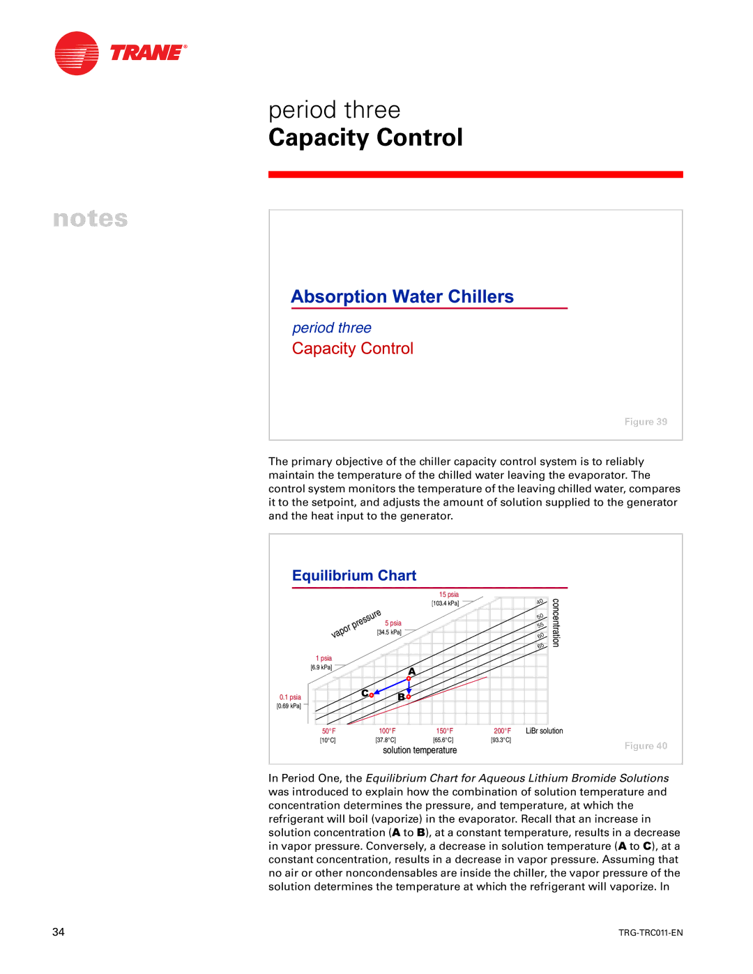
In Period One, the Equilibrium Chart for Aqueous Lithium Bromide Solutions was introduced to explain how the combination of solution temperature and concentration determines the pressure, and temperature, at which the refrigerant will boil (vaporize) in the evaporator. Recall that an increase in solution concentration ($ to %), at a constant temperature, results in a decrease in vapor pressure. Conversely, a decrease in solution temperature ($ to &), at a constant concentration, results in a decrease in vapor pressure. Assuming that no air or other noncondensables are inside the chiller, the vapor pressure of the solution determines the temperature at which the refrigerant will vaporize. In
34 |
|