period three
Capacity Control
notes
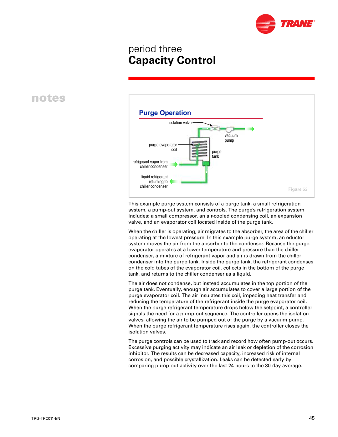
isolation valve 
purge evaporator coil
vacuum pump
purge tank
refrigerant vapor from chiller condenser
liquid refrigerant returning to chiller condenser
Figure 53
This example purge system consists of a purge tank, a small refrigeration system, a
When the chiller is operating, air migrates to the absorber, the area of the chiller operating at the lowest pressure. In this example purge system, an eductor system moves the air from the absorber to the condenser. Because the purge evaporator operates at a lower temperature and pressure than the chiller condenser, a mixture of refrigerant vapor and air is drawn from the chiller condenser into the purge tank. Inside the purge tank, the refrigerant condenses on the cold tubes of the evaporator coil, collects in the bottom of the purge tank, and returns to the chiller condenser as a liquid.
The air does not condense, but instead accumulates in the top portion of the purge tank. Eventually, enough air accumulates to cover a large portion of the purge evaporator coil. The air insulates this coil, impeding heat transfer and reducing the temperature of the refrigerant inside the purge evaporator coil. When the purge refrigerant temperature drops below the setpoint, a controller signals the need for a
The purge controls can be used to track and record how often
45 |