period four
Maintenance Considerations
notes | condenser inlet and outlet temperatures; and purge operation. Logs are a |
valuable tool for determining the onset of system problems. | |
| This data may be obtained either manually or in conjunction with a building |
| automation system. The chiller controller should be capable of providing this |
| information quickly and easily. An automated control system is an efficient way |
| to identify operating changes and schedule maintenance before they become a |
| problem. |
▲
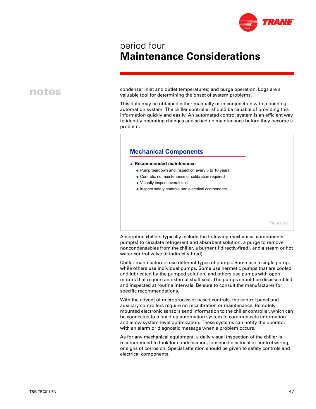
◆Pump teardown and inspection every 5 to 10 years
◆Controls: no maintenance or calibration required
◆Visually inspect overall unit
◆Inspect safety controls and electrical components
Figure 56
Absorption chillers typically include the following mechanical components: pump(s) to circulate refrigerant and absorbent solution, a purge to remove noncondensables from the chiller, a burner (if
Chiller manufacturers use different types of pumps. Some use a single pump, while others use individual pumps. Some use hermetic pumps that are cooled and lubricated by the pumped solution, and others use pumps with open motors that require an external shaft seal. The pumps should be disassembled and inspected at routine intervals. Be sure to consult the manufacturer for specific recommendations.
With the advent of
As for any mechanical equipment, a daily visual inspection of the chiller is recommended to look for condensation, loosened electrical or control wiring, or signs of corrosion. Special attention should be given to safety controls and electrical components.
47 |
