Installer’s Guide
NOTE:
Use 1/2" or larger PVC or CPVC pipe and fittings as re- quired for drain connections (fittings, pipe and solvent cement not provided).
NOTE:
A corrosion resistant condensate pump must be used if a pump is required for a specific drain system.
IMPORTANT:
The condensate drain should be installed with provi- sions to prevent winter
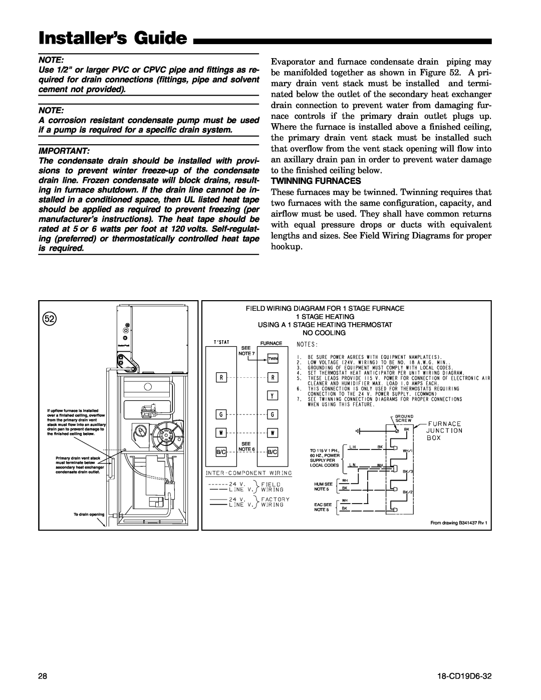
Evaporator and furnace condensate drain piping may be manifolded together as shown in Figure 52. A pri- mary drain vent stack must be installed and termi- nated below the outlet of the secondary heat exchanger drain connection to prevent water from damaging fur- nace controls if the primary drain outlet plugs up. Where the furnace is installed above a finished ceiling, the primary drain vent stack must be installed such that overflow from the vent stack opening will flow into an axillary drain pan in order to prevent water damage to the finished ceiling below.
TWINNING FURNACES
These furnaces may be twinned. Twinning requires that two furnaces with the same configuration, capacity, and airflow must be used. They shall have common returns with equal pressure drops or ducts with equivalent lengths and sizes. See Field Wiring Diagrams for proper hookup.
W
If upflow furnace is installed over a finished ceiling, overflow from the primary drain vent stack must flow into an auxillary drain pan to prevent damage to the finished ceiling below.
Primary drain vent stack ![]() must terminate below
must terminate below ![]() secondary heat exchanger condensate drain outlet.
secondary heat exchanger condensate drain outlet.
To drain opening
B/C
FIELD WIRING DIAGRAM FOR 1 STAGE FURNACE
1 STAGE HEATING
USING A 1 STAGE HEATING THERMOSTAT
NO COOLING
FURNACE
SEE
NOTE 7
![]() TWIN
TWIN
SEE |
|
|
|
|
| ||||
NOTE 6 | B/C |
|
| TO 115 V 1 PH., | |||||
|
|
|
|
|
|
| |||
|
|
|
|
|
|
|
|
| 60 HZ., POWER |
|
|
|
|
|
|
|
|
| SUPPLY PER |
|
|
|
|
|
|
|
|
| LOCAL CODES |
|
|
|
|
|
|
|
|
|
|
|
|
|
|
|
|
|
|
|
|
HUM SEE
NOTE 5
EAC SEE
NOTE 5
From drawing B341437 Rv 1
28 |