Basic Configuration via Browser Interface
LED Summary
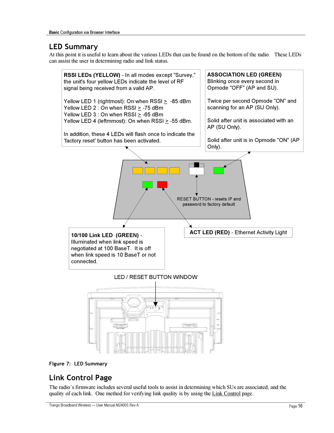
At this point it is useful to learn about the various LEDs that can be found on the bottom of the radio. These LEDs can assist the user in determining radio and link status.
RSSI LEDs (YELLOW) - In all modes except "Survey," the unit's four yellow LEDs indicate the level of RF signal being received from a valid AP.
Yellow LED 1 (rightmost): On when RSSI >
Yellow LED 2 : On when RSSI >
Yellow LED 3 : On when RSSI >
Yellow LED 4 (leftmmost): On when RSSI >
In addition, these 4 LEDs will flash once to indicate the 'factory reset' button has been activated.
ASSOCIATION LED (GREEN) Blinking once every second in Opmode "OFF" (AP and SU).
Twice per second Opmode "ON" and scanning for an AP (SU Only).
Solid after unit is associated with an AP (SU Only).
Solid after unit is in Opmode "ON" (AP Only).
RESET BUTTON - resets IP and
password to factory default
10/100 Link LED (GREEN) - Illuminated when link speed is negotiated at 100 BaseT. It is off when link speed is 10 BaseT or not connected.
ACT LED (RED) - Ethernet Activity Light
LED / RESET BUTTON WINDOW
Figure 7: LED Summary
Link Control Page
The radio’s firmware includes several useful tools to assist in determining which SUs are associated, and the quality of each link. One method for verifying link quality is by using the Link Control page.
Trango Broadband Wireless — User Manual M2400S Rev A | Page 16 |