Getting Started
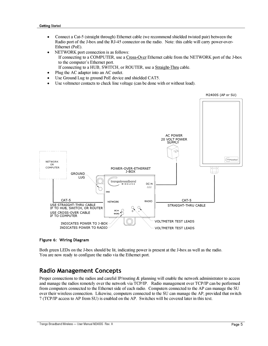
•Connect a
•NETWORK port connection is as follows:
If connecting to a COMPUTER, use a
If connecting to a HUB, SWITCH, or ROUTER, use a
•Plug the AC adapter into an AC outlet.
•Use Ground Lug to ground PoE device and shielded CAT5.
•Use voltmeter contacts to check line voltage (can be done with or without load).
M2400S (AP or SU)
NETWORK
OR
COMPUTER
AC POWER
20 VOLT POWER
SUPPLY
GROUND LUG
USE | |
IF TO HUB, SWITCH, OR ROUTER |
|
USE |
|
IF TO COMPUTER |
|
INDICATES POWER TO | VOLTMETER TEST LEADS |
| |
INDICATES POWER TO RADIO | VOLTMETER TEST LEADS |
Figure 6: Wiring Diagram
Both green LEDs on the
Radio Management Concepts
Proper connections to the radios and careful IP/routing & planning will enable the network administrator to access and manage the radios remotely over the network via TCP/IP. Radio management over TCP/IP can be performed from computers connected to the Ethernet side of each radio. Computers connected to the AP can manage the SU over their wireless connection. Likewise, computers connected to the SU can manage the AP, provided that switch 7 (TCP/IP access to AP from SU) is enabled on the AP. Switches will be covered later in this text.
Trango Broadband Wireless — User Manual M2400S Rev. A | Page 5 |