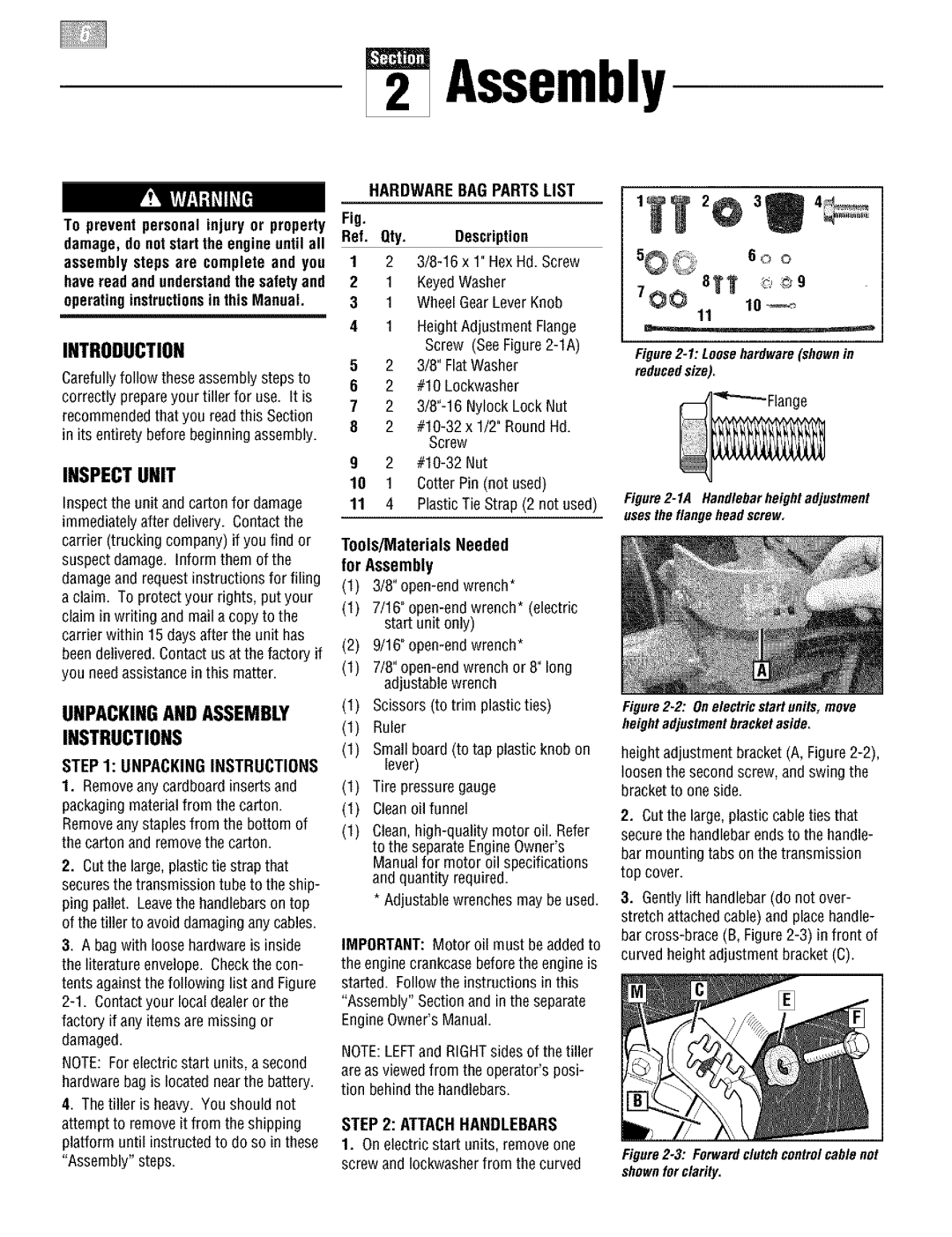
E666M, 664D specifications
Troy-Bilt is a trusted name in outdoor power equipment, and their line of tillers, including the E666M, 664D, and 665B models, exemplifies their commitment to quality and practicality. These tillers are designed to make soil preparation easier and more efficient, catering to both amateur gardeners and seasoned landscapers alike.The Troy-Bilt E666M is a robust machine tailored for ease of use and reliability. With a powerful engine, it delivers consistent performance, ensuring that users can tackle even the toughest soils. One of its standout features is the adjustable tilling width, which provides flexibility for various gardening needs. This tiller also boasts a Reverse Tillage feature, allowing the operator to break up stubborn soil with ease while enhancing control during operation.
The 664D model takes efficiency a step further with its durable construction and user-friendly design. This tiller is equipped with a dependable engine that provides ample power for deep soil cultivation. The 664D features self-propulsion technology, allowing users to maintain steady speed without exerting excessive effort. The adjustable depth settings further enhance soil penetration, making it possible to cultivate deep for extensive planting or surface till for lighter gardening tasks.
With the 665B, Troy-Bilt introduces advanced engineering for increased maneuverability and performance. This tiller features a patented belt-drive system that improves torque and ensures optimal power transfer to the tines. The 665B is also designed with comfort in mind, featuring ergonomic handles that reduce strain on the operator, making it ideal for longer gardening sessions. Its heavy-duty tines ensure exceptional soil mixing, while the adjustable tilling width and depth allow for customization according to specific gardening requirements.
All three tillers come equipped with Troy-Bilt's signature red oversized drag stake, enabling users to control tilling depth and improve stability during operation. They are designed with durable components that promise longevity and reliability, ensuring that they can withstand rigorous use season after season.
In summary, the Troy-Bilt E666M, 664D, and 665B tillers offer a variety of features and technologies that cater to every gardening need. With their reliable engines, user-friendly designs, and advanced tilling capabilities, these models embody the innovation and durability that Troy-Bilt is known for, making them excellent choices for anyone looking to elevate their gardening experience.

