Chapter 2
Board Installation
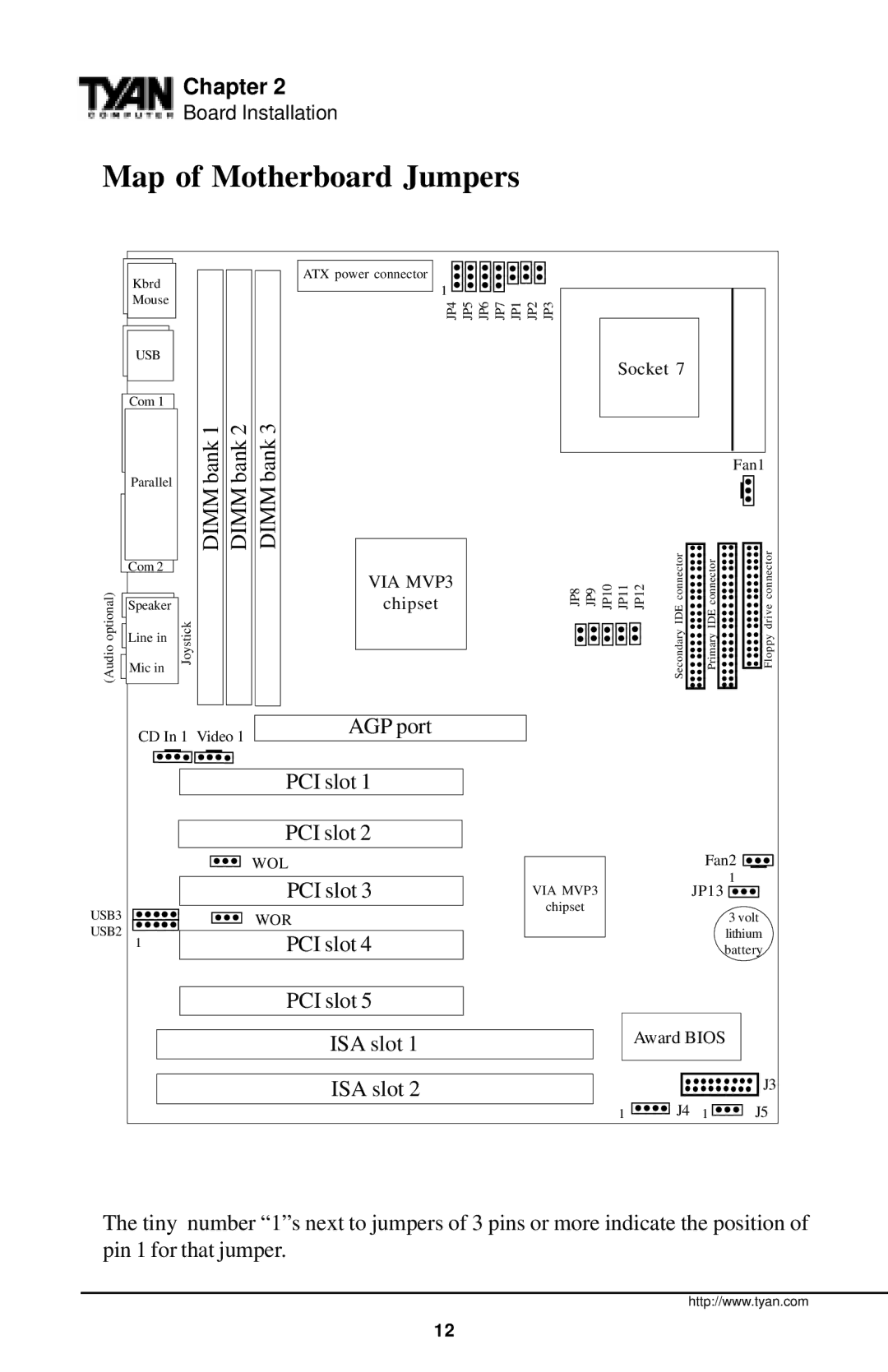
Map of Motherboard Jumpers
(Audio optional)
USB3
USB2
Kbrd | ATX power connector | |
1 | ||
Mouse | ||
JP4 JP5 JP6 JP7 JP1 JP2 JP3 | ||
| ||
USB |
|
Socket 7
Com 1
| 1 2 3 |
|
|
|
|
|
|
|
| ||
| bank | bank | bank |
|
|
|
|
|
|
| Fan1 |
Parallel |
|
|
|
|
|
|
|
| |||
DIMM | DIMM |
|
|
|
|
|
|
|
|
| |
Com 2 | VIA MVP3 |
|
|
|
|
| IDEconnector | IDEconnector | driveconnector | ||
| JP8 | JP9 | JP10 | JP11 | JP12 | ||||||
Speaker | chipset | ||||||||||
| DIMM | ||||||||||
Line in | Joystick |
|
|
|
|
|
|
| Secondary | Primary | Floppy |
Mic in |
|
|
|
|
|
|
| ||||
|
|
|
|
|
|
|
| ||||
|
|
|
|
|
|
|
|
| |||
CD In 1 Video 1 | AGP port |
|
|
|
|
|
|
|
| ||
|
|
|
|
|
|
|
|
| |||
|
|
| PCI slot 1 |
|
|
|
|
|
|
|
|
|
|
| PCI slot 2 |
|
|
|
|
|
|
|
|
|
|
| WOL |
|
|
|
|
|
| Fan2 | |
|
|
| PCI slot 3 | VIA MVP3 |
|
|
|
| JP13 | 1 | |
|
|
|
|
|
|
|
| ||||
|
|
| WOR | chipset |
|
|
|
|
|
| 3 volt |
|
|
|
|
|
|
|
|
|
| ||
1 |
|
| PCI slot 4 |
|
|
|
|
|
|
| lithium |
|
|
|
|
|
|
|
|
| battery | ||
|
|
| PCI slot 5 |
|
|
|
|
|
|
|
|
|
|
| ISA slot 1 |
|
|
|
| Award BIOS | |||
|
|
| ISA slot 2 |
|
|
|
|
|
|
| J3 |
|
|
|
|
|
|
| 1 |
| J4 | 1 | J5 |
The tiny number “1”s next to jumpers of 3 pins or more indicate the position of pin 1 for that jumper.
http://www.tyan.com
12
