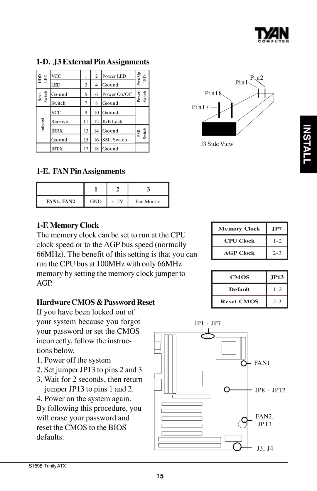
1-D. J3 External Pin Assignments
HDD |
| LED | VCC | 1 | 2 | Po wer LED | Pwr/Slp | LEDs |
|
|
|
|
|
| Pin2 | |
| LED | 3 | 4 | Gro und |
|
|
|
|
| Pin1 | ||||||
Reset |
| Switch | Gro und | 5 | 6 | Po wer On /Off | Power | Switch |
| Pin18 |
| |||||
| Switch | 7 | 8 | Gro und | Pin17 |
|
|
|
|
|
| |||||
|
|
|
|
|
|
|
|
|
|
| ||||||
|
|
| VCC | 9 | 10 | Gro und |
|
|
|
|
|
|
| |||
|
|
|
|
|
|
|
|
|
| |||||||
|
|
|
|
|
|
|
|
|
|
|
|
| ||||
| Infrared |
| Receive | 11 | 12 | K/B Lock |
|
|
|
|
|
|
|
|
|
|
|
| IRRX | 13 | 14 | Gro und | SMI | Switch |
|
|
|
|
|
|
|
| |
|
|
| Gro und | 15 | 16 | SM I Switch | J3 Side View | |||||||||
|
|
|
|
| ||||||||||||
|
|
| IRTX | 17 | 18 | Gro und |
|
| ||||||||
|
|
|
|
|
|
|
|
|
|
|
|
| ||||
1-E. FAN Pin Assignments
| 1 | 2 | 3 |
|
|
|
|
FAN1, FAN2 | GND | +12V | Fan Monitor |
|
|
|
|
| Memory Clock | JP7 | |
The memory clock can be set to run at the CPU | |||
|
| ||
CPU Clock | |||
clock speed or to the AGP bus speed (normally | |||
|
| ||
66MHz). The benefit of this setting is that you can | AGP Clock | ||
run the CPU bus at 100MHz with only 66MHz |
|
| |
|
| ||
memory by setting the memory clock jumper to |
|
| |
CMOS | JP13 | ||
AGP. | |||
|
| ||
Default | |||
| |||
Hardware CMOS & Password Reset |
|
| |
Reset CMOS | |||
|
|
|
If you have been locked out of |
|
|
|
|
|
|
|
|
|
|
|
|
|
|
|
|
|
|
|
|
| |
your system because you forgot |
|
|
|
|
|
|
| JP1 - JP7 | ||||||||||||||
your password or set the CMOS |
|
|
|
|
|
|
|
|
|
|
|
|
|
|
|
|
|
|
|
|
| |
|
|
|
|
|
|
|
|
|
|
|
|
|
|
|
|
|
|
|
|
| ||
incorrectly, follow the instruc- |
|
|
|
|
|
|
|
|
|
|
|
|
|
|
|
|
|
|
|
|
| |
|
|
|
|
|
|
|
|
|
|
|
|
|
|
|
|
|
|
|
|
| ||
tions below. |
|
|
|
|
|
|
|
|
|
|
|
|
|
|
|
|
|
|
|
|
| |
|
|
|
|
|
|
|
|
|
|
|
|
|
|
|
|
|
|
|
|
| ||
1. Power off the system |
|
|
|
|
|
|
|
|
|
|
|
|
|
|
|
|
|
|
|
|
| FAN1 |
|
|
|
|
|
|
|
|
|
|
|
|
|
|
|
|
|
|
|
| |||
2. Set jumper JP13 to pins 2 and 3 |
|
|
|
|
|
|
|
|
|
|
|
|
|
|
|
|
|
|
|
|
| |
|
|
|
|
|
|
|
|
|
|
|
|
|
|
|
|
|
|
|
|
|
| |
3. Wait for 2 seconds, then return |
|
|
|
|
|
|
|
|
|
|
|
|
|
|
|
|
|
|
|
|
|
|
|
|
|
|
|
|
|
|
|
|
|
|
|
|
|
|
|
|
|
|
|
| |
jumper JP13 to pins 1 and 2. |
|
|
|
|
|
|
|
|
|
|
|
|
|
|
|
|
|
|
|
|
| JP8 - JP12 |
|
|
|
|
|
|
|
|
|
|
|
|
|
|
|
|
|
|
|
| |||
|
|
|
|
|
|
|
|
|
|
|
|
|
|
|
|
|
|
|
| |||
4. Power on the system again. |
|
|
|
|
|
|
|
|
|
|
|
|
|
|
|
|
|
|
|
|
| |
|
|
|
|
|
|
|
|
|
|
|
|
|
|
|
|
|
|
|
|
| ||
By following this procedure, you |
|
|
|
|
|
|
|
|
|
|
|
|
|
|
|
|
|
|
|
| FAN2, | |
|
|
|
|
|
|
|
|
|
|
|
|
|
|
|
|
|
|
|
| |||
|
|
|
|
|
|
|
|
|
|
|
|
|
|
|
|
|
|
|
| |||
will erase your password and |
|
|
|
|
|
|
|
|
|
|
|
|
|
|
|
|
|
|
|
| ||
|
|
|
|
|
|
|
|
|
|
|
|
|
|
|
|
|
| |||||
reset the CMOS to the BIOS |
|
|
|
|
|
|
|
|
|
|
|
|
|
|
|
|
|
|
|
| JP13 | |
|
|
|
|
|
|
|
|
|
|
|
|
|
|
|
|
|
| |||||
|
|
|
|
|
|
|
|
|
|
|
|
|
|
|
|
|
|
|
|
| ||
defaults. |
|
|
|
|
|
|
|
|
|
|
|
|
|
|
|
|
|
|
|
| J3, J4 | |
|
|
|
|
|
|
|
|
|
|
|
|
|
|
|
|
|
|
|
| |||
S1598 Trinity ATX |
|
|
|
|
|
|
|
|
|
|
|
|
|
|
|
|
|
|
|
| ||
|
|
|
|
|
|
|
|
|
|
|
|
|
|
|
|
|
|
|
| |||
|
|
|
|
|
|
|
|
|
|
|
|
|
|
|
|
|
|
| ||||
|
|
|
|
|
|
|
|
|
|
|
|
|
|
|
|
|
| |||||
|
|
|
|
|
|
|
|
|
|
|
|
|
|
|
|
|
|
|
|
| ||
INSTALL
15