Installation and Operation Guide
2. DESCRIPTION OF THE FRONT/REAR VIEW
2.1 Front Panel and Rear Panel
-- Front Panel --
1 |
-- Rear Panel --
2 | 3 | 4 | 5 |
6 | 7 | 8 |
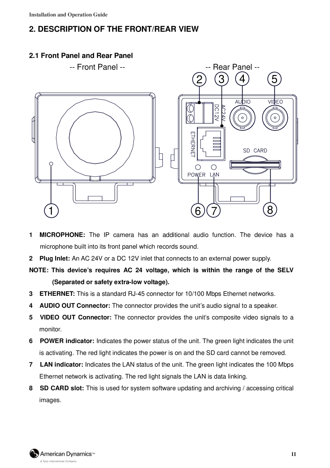
1MICROPHONE: The IP camera has an additional audio function. The device has a microphone built into its front panel which records sound.
2Plug Inlet: An AC 24V or a DC 12V inlet that connects to an external power supply.
NOTE: This device’s requires AC 24 voltage, which is within the range of the SELV (Separated or safety
3ETHERNET: This is a standard
4AUDIO OUT Connector: The connector provides the unit’s audio signal to a speaker.
5VIDEO OUT Connector: The connector provides the unit’s composite video signals to a monitor.
6POWER indicator: Indicates the power status of the unit. The green light indicates the unit is activating. The red light indicates the power is on and the SD card cannot be removed.
7LAN indicator: Indicates the LAN status of the unit. The green light indicates the 100 Mbps Ethernet network is activating. The red light signals the LAN is data linking.
8SD CARD slot: This is used for system software updating and archiving / accessing critical images.
11
