Chapter 2. Data Structure
2.Data Structure
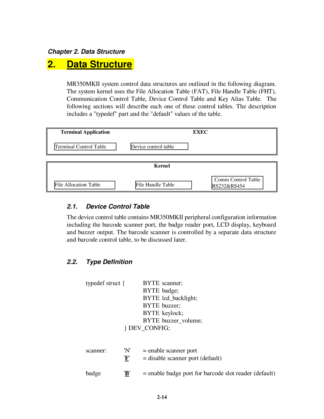
MR350MKII system control data structures are outlined in the following diagram. The system kernel uses the File Allocation Table (FAT), File Handle Table (FHT), Communication Control Table, Device Control Table and Key Alias Table. The following sections will describe each one of these control tables. The description includes a "typedef" part and the "default" values of the table.
Terminal Application
Terminal Control Table
EXEC
Device control table
File Allocation Table
Kernel
File Handle Table
Comm Control Table RS232&RS454
2.1.Device Control Table
The device control table contains MR350MKII peripheral configuration information including the barcode scanner port, the badge reader port, LCD display, keyboard and buzzer output. The barcode scanner is controlled by a separate data structure and barcode control table, to be discussed later.
2.2.Type Definition
typedef struct { | BYTE scanner; | |
|
| BYTE badge; |
|
| BYTE lcd_backlight; |
|
| BYTE buzzer; |
|
| BYTE keylock; |
|
| BYTE buzzer_volume; |
| } DEV_CONFIG; | |
scanner: | 'N' | = enable scanner port |
| 'F' | = disable scanner port (default) |
badge | 'B' | = enable badge port for barcode slot reader (default) |