2-6 Installation
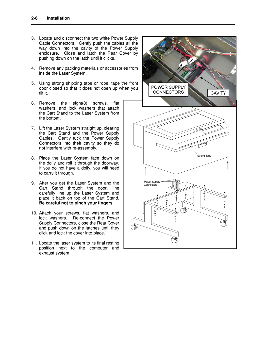
3.Locate and disconnect the two white Power Supply Cable Connectors. Gently push the cables all the way down into the cavity of the Power Supply enclosure. Close and latch the Rear Cover by pushing down on the latch until it clicks.
4.Remove any packing materials or accessories from inside the Laser System.
5.Using strong shipping tape or rope, tape the front door closed so that it does not open up when you tilt it.
6.Remove the eight(8) screws, flat washers, and lock washers that attach the Cart Stand to the Laser System from the bottom.
7.Lift the Laser System straight up, clearing the Cart Stand and the Power Supply Cables. Gently tuck the Power Supply
Connectors into their cavity so they do not interfere with
8.Place the Laser System face down on the dolly and roll it through the doorway. If you do not have a dolly, you will need to carry it through.
9.After you get the Laser System and the Cart Stand through the door, line carefully line up the Laser System and place it back on top of the Cart Stand. Be careful not to pinch your fingers.
10.Attach your screws, flat washers, and lock washers.
Supply Connectors, close the Rear Cover and push down on the latches until they click and lock the cover into place.
11.Locate the laser system to its final resting position next to the computer and exhaust system.