System Operation 3-3
The “Focal Range” of the lens, where the beam is considered to be “in focus”, is equivalent to +/- 5% above and below the focus point. Shorter lenses produce a smaller spot size but also have a very narrow focal range. This means that it would only be useful for engraving very flat objects. The longer lenses have a much wider range of focus but also produce a larger spot size that would prohibit the engraving of fine detail. This can be related to trying to write small text with a wide, felt tip marker. There are pros and cons to the different lenses that are available for different applications. Please refer to the Appendices section on available lenses and their operating characteristics.
“Wattage” signifies the amount of heat energy that the laser light is producing over a period of time. Laser energy is measured with a laser power meter that measures the unfocused laser beam’s heat output over a calibrated period of time.
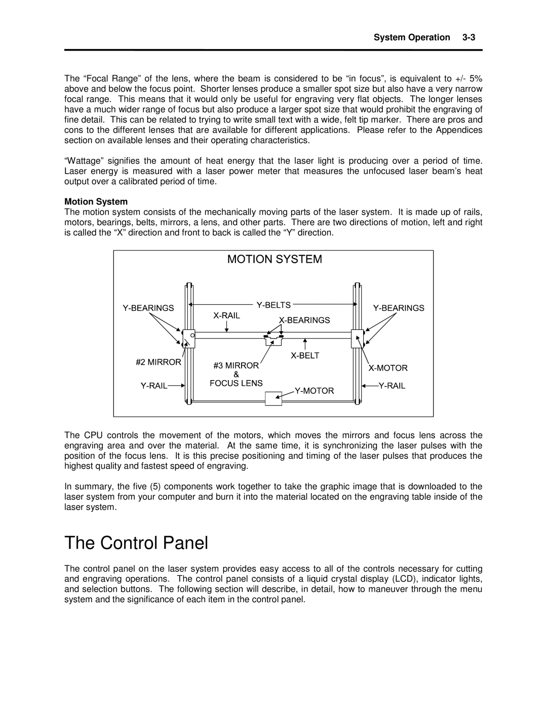
Motion System
The motion system consists of the mechanically moving parts of the laser system. It is made up of rails, motors, bearings, belts, mirrors, a lens, and other parts. There are two directions of motion, left and right is called the “X” direction and front to back is called the “Y” direction.
The CPU controls the movement of the motors, which moves the mirrors and focus lens across the engraving area and over the material. At the same time, it is synchronizing the laser pulses with the position of the focus lens. It is this precise positioning and timing of the laser pulses that produces the highest quality and fastest speed of engraving.
In summary, the five (5) components work together to take the graphic image that is downloaded to the laser system from your computer and burn it into the material located on the engraving table inside of the laser system.
The Control Panel
The control panel on the laser system provides easy access to all of the controls necessary for cutting and engraving operations. The control panel consists of a liquid crystal display (LCD), indicator lights, and selection buttons. The following section will describe, in detail, how to maneuver through the menu system and the significance of each item in the control panel.