Installation 2-11
Helpful Tip
If you are having any problems printing a font and you cannot figure out what is going on, select the font and “convert to curves” or “convert to paths” in your graphics software. This will convert the font into a bitmapped image and will print correctly to the laser system. Refer to your graphics software on how to convert fonts.
As you can see, we strongly recommend the use of True Type fonts only. Usually, most graphics programs, such as CorelDraw come with hundreds of fonts that you can install. For the average user there is more than enough to choose from.
Making the Connections
Please use the parallel cable supplied with the system. It is a
Please make the following connections in the exact order described otherwise static electricity can damage the computer and/or the laser system’s electronics.
•Connect the systems Power Cord and your computer Power Cord to the electrical outlet(s). Do not turn on either unit at this time.
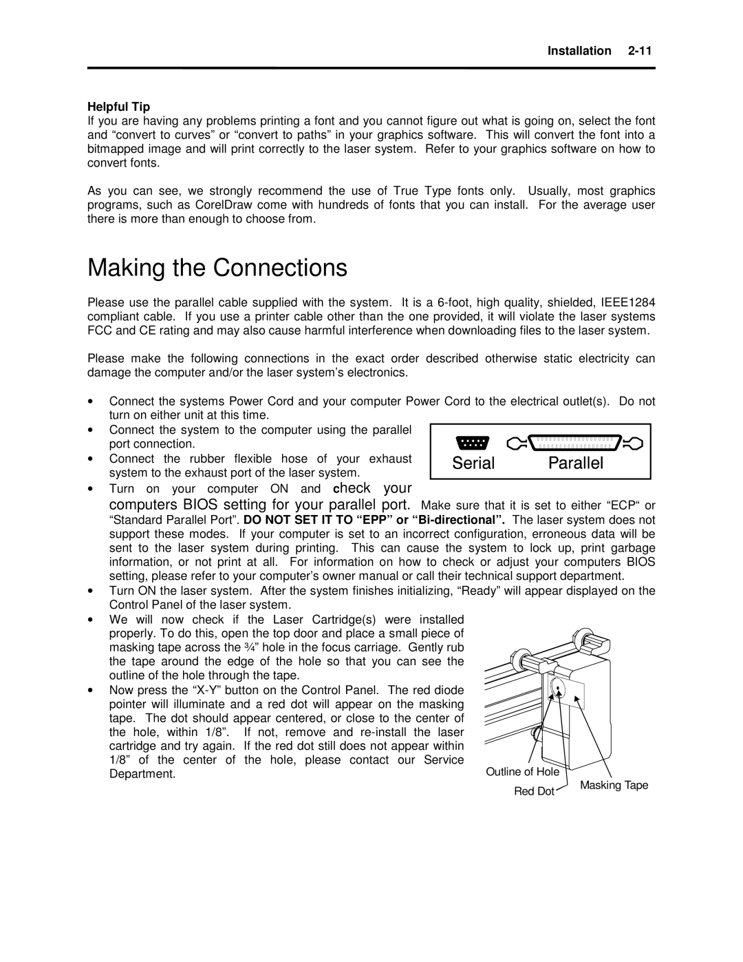
•Connect the system to the computer using the parallel
port connection.
•Connect the rubber flexible hose of your exhaust system to the exhaust port of the laser system.
•Turn on your computer ON and check your
computers BIOS setting for your parallel port. Make sure that it is set to either “ECP“ or
“Standard Parallel Port”. DO NOT SET IT TO “EPP” or
•Turn ON the laser system. After the system finishes initializing, “Ready” will appear displayed on the Control Panel of the laser system.
•We will now check if the Laser Cartridge(s) were installed
properly. To do this, open the top door and place a small piece of masking tape across the ¾” hole in the focus carriage. Gently rub the tape around the edge of the hole so that you can see the outline of the hole through the tape.
• Now press the
Red Dot | Masking Tape |
|