PLEASE READ THIS MANUAL BEFORE INSTALLING AND USING APPLIANCE
WHAT TO DO IF YOU SMELL GAS
Homeowner’s Installation and Operating Manual
INSTALLER / CONSUMER SAFETY INFORMATION
20012950
Stardance Direct Vent - Rear Vent Gas Heaters
Table of Contents
Installation & Operating Instructions
Stardance Direct Vent / Rear Vent Certified to
ANSI Z21.88-2005 / CSA Z2.33-2005 Vented Gas Fireplace Heaters
Stardance Direct Vent - Rear Vent Gas Heaters
Installation of Carbon Monoxide Detectors
Requirements for the Commonwealth of Massachusetts
MANUFACTURER REQUIREMENTS
Approved Carbon Monoxide Detectors
Stove Dimensions - Stardance Direct Vent Gas Heater
Fig. 1 Stardance dimensions
20012950
229 mm C Valve L Inlet
Installation Requirements
area to accomplish a safe and effective installation
Locating the Stove
Clearance Requirements
Parallel Installation Minimum Clearance
Corner Installation Minimum Clearance and Flue Centerline
Mantel Clearances
and Flue Centerline
Gas Specifications
Gas Inlet and Manifold Pressures
High Elevations
Horizontal Termination
Restrictor Plate Adjustment for Extended Pipe Runs
Restrictor Plate Adjustment
Vertical Termination
All Vertical
Vent Termination Clearances
Stardance Direct Vent - Rear Vent Gas Heaters
Location of Vent Termination
20012950
Canadian Installations1
US Installations2
General Venting Information - Termination Location
Stardance Direct Vent - Rear Vent Gas Heaters
Termination Clearances
D C C
Stardance Direct Vent - Rear Vent Gas Heaters
20012950
Below-Grade Installation
12” Non-adjustable Pipe
12” - 18” Adjustable Pipe
24” Non-adjustable Pipe
Installation
Install Optional Fan Kit #2960/FK28
Fan Kit Contents
Unpack the Stove
Venting System Assembly General Information
Rear Vent
Stardance Direct Vent - Rear Vent Gas Heaters
20012950
Side Wall Termination Assembly
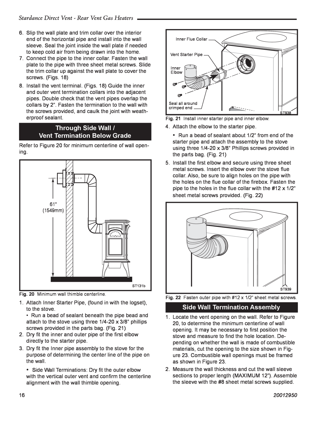
Through Side Wall Vent Termination Below Grade
Stardance Direct Vent - Rear Vent Gas Heaters
1549mm
Stardance Direct Vent - Rear Vent Gas Heaters
6. Install the elbow using 3 sheet metal screws at each joint
20012950
Stardance Direct Vent - Rear Vent Gas Heaters
Vent Termination Below Grade
20012950
Vertical Through the Roof Vent Assembly
Vertical Through Existing Chimney
Fireplace Vent Termination Clearances
9³⁄₈” x 9³⁄₈” 240 x 240mm
All vegetation within 36” 914 mm that may interfere with the draft
Stardance Direct Vent - Rear Vent Gas Heaters
20012950
Fireplace Installation Requirements
Fireplace Installations Using Existing Wood Stove Chimneys
Stardance Direct Vent - Rear Vent Gas Heaters
20012950
Installation Instructions
Framing Dimension Table
Selkirk Direct-Temp Metalbestos Direct Vent System
Appliance Adapter AAV
Fig. 39 Selkirk venting components
Offsets
Stardance Direct Vent - Rear Vent Gas Heaters
20012950
Horizontal Installation
Adjustable Length AJ
Supporting DIRECT-TEMP Horizontal Support
Fire Stopping
Stardance Direct Vent - Rear Vent Gas Heaters
Vertical Installation Fig
20012950
screws through the support collar and the outer wall of the pipe
Stardance Direct Vent - Rear Vent Gas Heaters
20012950
Complete the Assembly
Install ON/OFF Switch
Connect the Gas Supply Line
Burner Information
Install the Front Plate
This completes assembly of the Stardance Rear Vent stove
Thermostat Connection
Use only a thermostat rated for 500 - 750 millivolts
Install the Log Set
AGED LOGS
Stardance Direct Vent - Rear Vent Gas Heaters
20012950
Stardance Direct Vent - Rear Vent Gas Heaters
20012950
LG494
Top Log
Flame & Temperature Adjustment
CAUTION DO NOT TOUCH DOORS WHEN HOT
Operation
Your First Fire
Flame Characteristics
Stardance Direct Vent - Rear Vent Gas Heaters
20012950
Fig. 58 Correct pilot and burner flame patterns
FOR YOUR SAFETY READ BEFORE LIGHTING
may result causing property damage, personal injury or loss of life
Lighting And Operating Instructions
To Turn Off Gas To Heater
Troubleshooting the Gas Control System SDDVT Series
Symptom
SIT NOVA 820 MILLIVOLT VALVE
Possible Causes
Shut Off Procedure
Delay Timer Mode
Instructions for RF Comfort Control Valve
Operation
Change Between F/C Temperature Units
Disable Thermostat Function
Troubleshooting
Service Action
Comfort Valve System Control Sequence Of Operation With Transmitter
Stardance Direct Vent - Rear Vent Gas Heaters
20012950
Local Path
Stardance Direct Vent - Rear Vent Gas Heaters
Auto Path
20012950
Conversion Precautions
Conversion Procedure
Fuel Conversion Instructions
Valve Conversion SDDVR Series Models
Pilot Orifice Conversion
Pilot Type
Pilot type
Stardance Direct Vent - Rear Vent Gas Heaters
Burner Orifice Conversion
All Models
Stardance Direct Vent - Rear Vent Gas Heaters
20012950
Table 2. Injector Orifice Size Matrix
Conversion to LP
Input BTU/h
Conversion to Natural Gas
Maintenance
Logset and Burner Cleaning and Inspection
Cleaning the Glass
Glass Replacement
Gasket Replacement
Stove Disassembly
Inspect the Vent System Annually
Check the Gas Flame Regularly
Wiring Diagrams
Fig. 82 On/off switch and optional thermostat circuit
POWER
Stardance Direct Vent - Rear Vent Gas Heaters
Stardance Direct Vent/Rear Vent Gas Heater
Models SDDVR Series SDDVRCB, SDDVREB, SDDVRMB, SDDVRBS, SDDVRCH
SDDVRVG, SDDVRBD
SDDVRC Series SDDVRCCB, SDDVRCEB, SDDVRCMB, SDDVRCBS, SDDVRCCH
Stardance Direct Vent/Rear Vent Gas Heater continued
Description
SDDVR/SDDVRC
Stardance Direct Vent - Rear Vent Gas Heaters
Fuel Conversion Kits
Stardance Direct Vent/Rear Vent Gas Heater continued
Stardance Direct Vent - Rear Vent Gas Heaters
Description
Optional Accessories
Remote Controls
Maintenance
Installation
Stardance Direct Vent - Rear Vent Gas Heaters
20012950
PRODUCT COVERED BY THIS WARRANTY
LIMITED LIFETIME WARRANTY
20012950
Efficiency Ratings
EnerGuide Ratings
Fireplace Efficiency %
CFM Corporation