Pinnacle & Stardance Direct Vent - Rear Vent Gas Heaters

Installation

Unpack the Stove

The stove is shipped fully assembled on its back. Unpack the stove and carefully set it upright.

CAUTION

Porcelain enamelled surfaces are fragile. Handle porcelain enamelled castings tenderly. Familiarize yourself with the assembly steps before you begin and proceed with deliberation and care. If possible, have assistance available.

Place enamelled castings on a soft, cushioned surface until you are ready to assemble.

Avoid contact between the castings and other hard surfaces or objects.

NOTE: Verify the two relief doors (located on top of the firebox) are properly seated on the gasket. The doors sit flush on the gasket, and should lift easily from the seal around the opening.

If you are not installing a fan, proceed to the appropriate vent assembly section.

Install Optional Fan Kit #2960/FK28

Fan Kit Contents:

#10 x 1/2" phillips screws, 6

Control Knob

Retainer Collar

Snapstat

Snapstat Bracket

Blower Assembly w/ Rheostat Control

NOTE: The Rheostat Assembly and the Snapstat Assembly are not used on RF Models.

For RF Models only: Follow Step 3, then run the spliced female leads to the front of the stove and attach to PC board of RF valve. Then follow Step 5.

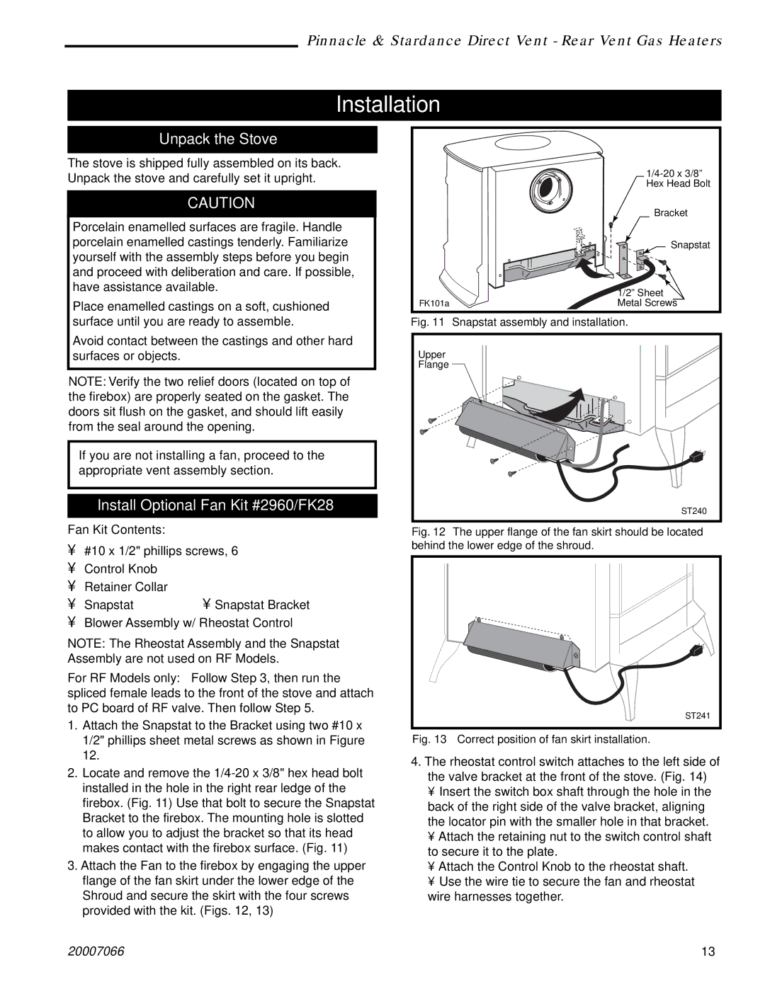
1.Attach the Snapstat to the Bracket using two #10 x 1/2" phillips sheet metal screws as shown in Figure 12.

2.Locate and remove the 1/4-20 x 3/8" hex head bolt installed in the hole in the right rear ledge of the firebox. (Fig. 11) Use that bolt to secure the Snapstat Bracket to the firebox. The mounting hole is slotted to allow you to adjust the bracket so that its head makes contact with the firebox surface. (Fig. 11)

3.Attach the Fan to the firebox by engaging the upper flange of the fan skirt under the lower edge of the Shroud and secure the skirt with the four screws provided with the kit. (Figs. 12, 13)


1/4-20 x 3/8”


Hex Head Bolt


Bracket


Snapstat


1/2” Sheet

FK101a

Metal Screws

Fig. 11

Snapstat assembly and installation.

Upper


Flange


ST240

Fig. 12 The upper flange of the fan skirt should be located behind the lower edge of the shroud.

ST241

Fig. 13 Correct position of fan skirt installation.

4.The rheostat control switch attaches to the left side of the valve bracket at the front of the stove. (Fig. 14)

Insert the switch box shaft through the hole in the back of the right side of the valve bracket, aligning the locator pin with the smaller hole in that bracket.

Attach the retaining nut to the switch control shaft to secure it to the plate.

Attach the Control Knob to the rheostat shaft.

Use the wire tie to secure the fan and rheostat wire harnesses together.

20007066

13

Page 13
Image 13
Vermont Casting SDVR, PDV20: 3920 Installation, Unpack the Stove, Install Optional Fan Kit #2960/FK28, Fan Kit Contents

3966, 4080, 3926, 3936, 3960 specifications

Vermont Casting is renowned for its craftsmanship and quality in the hearth industry, particularly with its range of wood and gas stoves. Among its standout models are the 4065, 4075, 4070, 3976, and 3970. Each of these models presents unique features and advanced technologies that cater to a variety of heating needs and preferences.

The Vermont Casting 4065 model is designed with efficiency and usability in mind. Its advanced air management system allows for precise control over combustion, ensuring that homeowners enjoy a longer burn time while minimizing emissions. The large glass door provides an excellent view of the fire, making it a centerpiece in any room. Additionally, the 4065 is built from heavy-duty cast iron, which not only enhances durability but also retains heat longer.

Moving on to the 4075 model, this stove offers an impressive heat output, making it suitable for larger spaces. The 4075 incorporates a unique catalytic combustor, which boosts efficiency by enabling cleaner burns and reducing smoke output. This model also features a user-friendly ash removal system, simplifying maintenance and enhancing user experience.

The 4070 model stands out with its modern design and customizable options. It comes in various colors and finishes, allowing homeowners to tailor it to their interior design style. Like the other models, it emphasizes efficiency with a built-in heat exchanger, maximizing heat transfer to the surrounding space and ensuring optimal comfort.

The Vermont Casting 3976 is a powerhouse of innovation. Equipped with Vermont Casting’s signature cast iron construction, it provides exceptional heat retention and distribution. It features a powerful blower option that can be added for enhanced heat circulation, making it ideal for larger homes or open floor plans. The 3976 also boasts an easy-to-use control panel that allows for intuitive operation.

Finally, the 3970 model is a versatile choice for those seeking a balance of size and efficiency. It offers a compact design without sacrificing performance, making it ideal for smaller rooms. The 3970 includes the same advanced air control system found in larger models, ensuring efficient combustion and heat output.

In summary, Vermont Casting’s 4065, 4075, 4070, 3976, and 3970 models exemplify the perfect blend of traditional craftsmanship and modern technology. With exceptional features such as catalytic combustors, advanced air management, and customizable designs, these stoves offer both aesthetic appeal and functional efficiency, meeting a range of heating needs for contemporary homeowners.