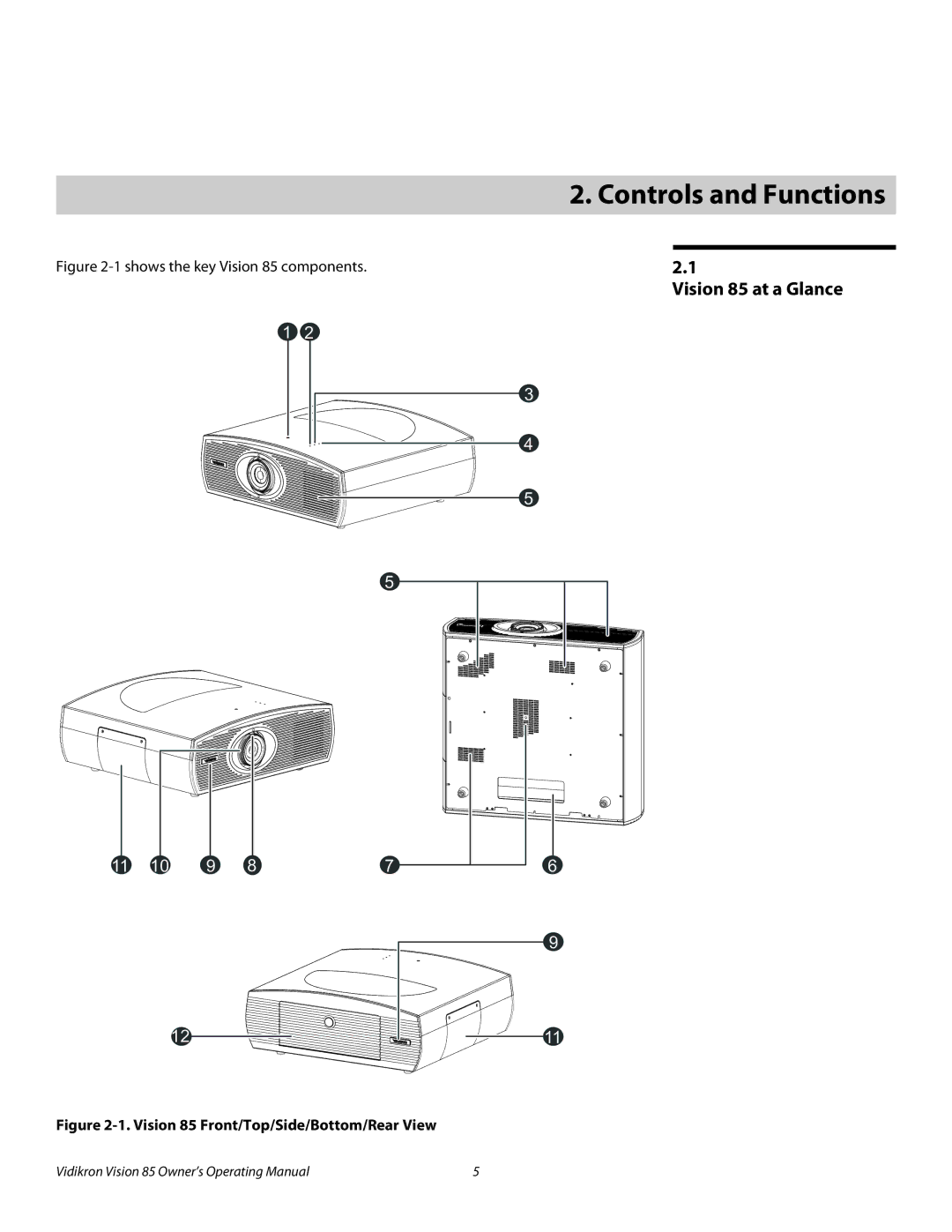
Manuals
/
Brands
/
TV and Video
/
Projection Television
/
Vidikron
/
TV and Video
/
Projection Television
Vidikron
Model 85
2. Controls and Functions
1
17
100
100
Download
100 pages, 4.95 Mb
Vidikron Vision
8
5 Owner’s Operating Manual
5
PRE
L
IMINAR
Y
2.1
Vision 85 at a Glance
Figure 2-1 shows the key Vision
8
5 components.
Figure 2-1. Vision 85 Fron
t/Top/Side/Bottom/Rear View
2. Controls and Functions
11
9
10 6
3
4
5
5
2
1
11
12
8
7
9
Contents
Main
Page
TWO YEAR LIMITED WARRANTY
For Projectors, Video Processors and Controllers
Page
VIDIKRON PRODUCT INFORMATION RETAIN THIS INFORMATION FOR YOUR RECORDS
Safety Precautions
Page
Page
Page
Page
Page
Page
1.1 About This Manual
1.2 Using This Manual
WARNING DANGER!
1.3 Description, Features and Benefits
Page
2.1 Vision 85 at a Glance
2. Controls and Functions
Page
2.2 Vision 85 Rear Panel
1 2 3 4 5 6
2.3 VHD Controller Front Panel
1 2 3
2.4 VHD Controller Rear Panel
Page
Controls and Functions
Vidikron Vision 85 Owners Operating Manual 11
2.5 Vision 85 Remote Control Unit
Figure 2-5. VHD Controller/Vision 85 Remote Control
Page
Page
2.6 Vision 85 Built-In Keypad
3.1 Remote Control
Page
3.2 Quick Setup
Installation should be performed by a qualified custom video installation specialist.
Table 3-1. Installation Overview
3.3 Installation Considerations
Table 3-1. Installation Overview (continued)
Table 3-2. Projector Installation Options
Table 3-3. Throw Ratios for the Vision 85 Series
Ceiling Installation
Floor Installation
Page
Page
Page
Page
Page
Page
3.5 Mounting the Vision 85
3.6 Connections to the Vision 85 and VHD Controller
Page
30 Vidikron Vision 85 Owners Operating Manual
Digital (DTV) RGB or Component Video Connections: See Figure 3-12.
Red/Pr Green/Y Blue/Pb Horiz Vert
Figure 3-12. Digital (DTV) RGB or Component Video Connections
DTV or Progressive Component (YPbPr) Source
Vidikron Vision 85 Owners Operating Manual 31
Analog (Computer) RGB Connections: See Figure 3-13.
Red Green Blue Horiz Vert
Personal Computer
Figure 3-13. Analog RGB Connections
32 Vidikron Vision 85 Owners Operating Manual
Composite/S-Video/Component Video Connections: See Figure 3-14.
Pb Pr Y
Figure 3-14. Composite, S-Video and Component Video Connections
DVD Player, VCR, Satellite Receiver, Laser Disc etc.
to Automation/ Control System or PC
34 Vidikron Vision 85 Owners Operating Manual
Connecting 12-Volt Trigger Outputs to External Equipment
AC Input
AutoScope Lens Motor (Rear)
INPUTS
OUTPUTS
VHD Controller Rear Panel
Ring = +5V Tip = IR Input Sleeve = Ground (3.5-mm mini phono plug)
IR Receiver Remote Control
3.7 Turning on the Power
Current Source Format
Component SD NTSC 480i 16:9 V85
Input Resolution
3.8 Adjusting the Picture Orientation
Focus
3.9 Primary Lens Adjustments
Zoom in
Zoom out
3.10 Installing and Adjusting the CineWide Anamorphic Lens
Page
Page
Page
Page
Page
Page
Page
Wrong Position Correct Position
Page
Operation
Input Source
Calibration
ISF Presets
Input Position
Picture
7
Table 4-1. Aspect Ratio Settings
Table 4-1. Aspect Ratio Settings (continued)
Page
Page
Page
Page
7
Page
Page
Page
Page
Page
Page
Operation
Vidikron Vision 85 Owners Operating Manual 63
4.3 On-Screen Menus for 1080i (Digital) or 1080p Signals
Language
Options
HD/RGB Adj.
White Balance
Page
Table 4-2. Default Picture Memory Settings for Digital 1080i and 1080p Sources
Table 4-2. Default Picture Memory Settings for Digital 1080i and 1080p Sources (continued)
Table 4-3. Effects of Primary Color Hue Adjustments
Page
Page
Page
Page
Page
5.1 Lamp Replacement
5.2 Troubleshooting Tips
Table 5-1. Troubleshooting Chart
Table 5-1. Troubleshooting Chart (continued)
Page
6.1 RS-232 Connection and Port Configuration
6.2 Serial Command Syntax
Table 6-1. Serial Commands
Page
Page
Page
Page
Page
7.1 Vision 85 Specifications
Table 7-1 lists the Vision 85 specifications.
Table 7-1. Vision 85 Specifications
Table 7-1. Vision 85 Specifications (continued)
7.2 VHD Controller Specifications
Table 7-2 lists the VHD Controller specifications.
Table 7-2. VHD Controller Specifications
7.3 Vision 85 Dimensions