Controls and Functions
.cover lamp the off pull to screw the Remove
Remove the screw to pull off the lamp cover.
SERVICE PORT
AUTHORIZED
PERSONNEL ONLY
![]()
![]()
![]()
![]() L
L ![]()
![]()
![]()
![]()
![]()
![]()
![]()
![]() L
L ![]()
![]()
![]()
![]()
1
2 | 3456 | 7 8 9 | 10 |
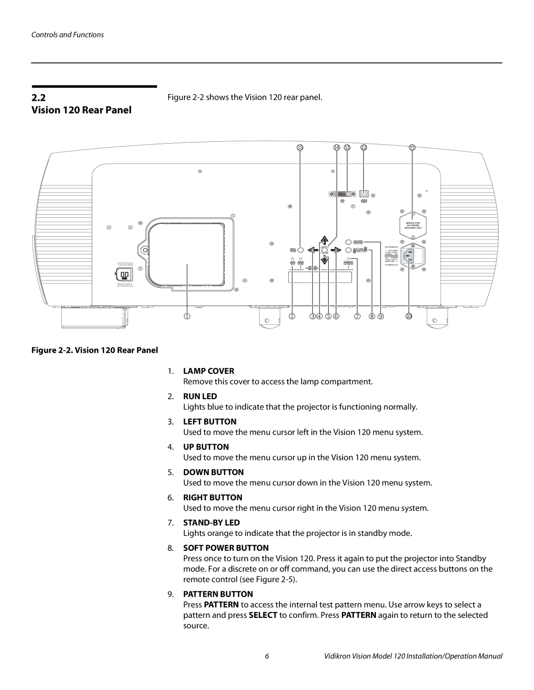
Figure 2-2. Vision 120 Rear Panel
1.LAMP COVER
Remove this cover to access the lamp compartment.
2.RUN LED
Lights blue to indicate that the projector is functioning normally.
3.LEFT BUTTON
Used to move the menu cursor left in the Vision 120 menu system.
4.UP BUTTON
Used to move the menu cursor up in the Vision 120 menu system.
5.DOWN BUTTON
Used to move the menu cursor down in the Vision 120 menu system.
6.RIGHT BUTTON
Used to move the menu cursor right in the Vision 120 menu system.
7.
Lights orange to indicate that the projector is in standby mode.
8. SOFT POWER BUTTON
Press once to turn on the Vision 120. Press it again to put the projector into Standby mode. For a discrete on or off command, you can use the direct access buttons on the remote control (see Figure
9.PATTERN BUTTON
Press PATTERN to access the internal test pattern menu. Use arrow keys to select a pattern and press SELECT to confirm. Press PATTERN again to return to the selected source.
6 | Vidikron Vision Model 120 Installation/Operation Manual |
