Wayne-Dalton 9700 installation instructions End Brackets, Securing Center Bracket, Assembly, side

Models: 9700

1 32
Download 32 pages 17.33 Kb
Page 18
Image 18
End Brackets

17

Tools Needed: Power Drill

End Brackets

IMPORTANT: Warning Tags must be securely attached to both End Brackets.

Splines

Groove

Disconnect

Cable Guide

Hole

7/16” Wrench

7/16” Socket

Driver

Step Ladder

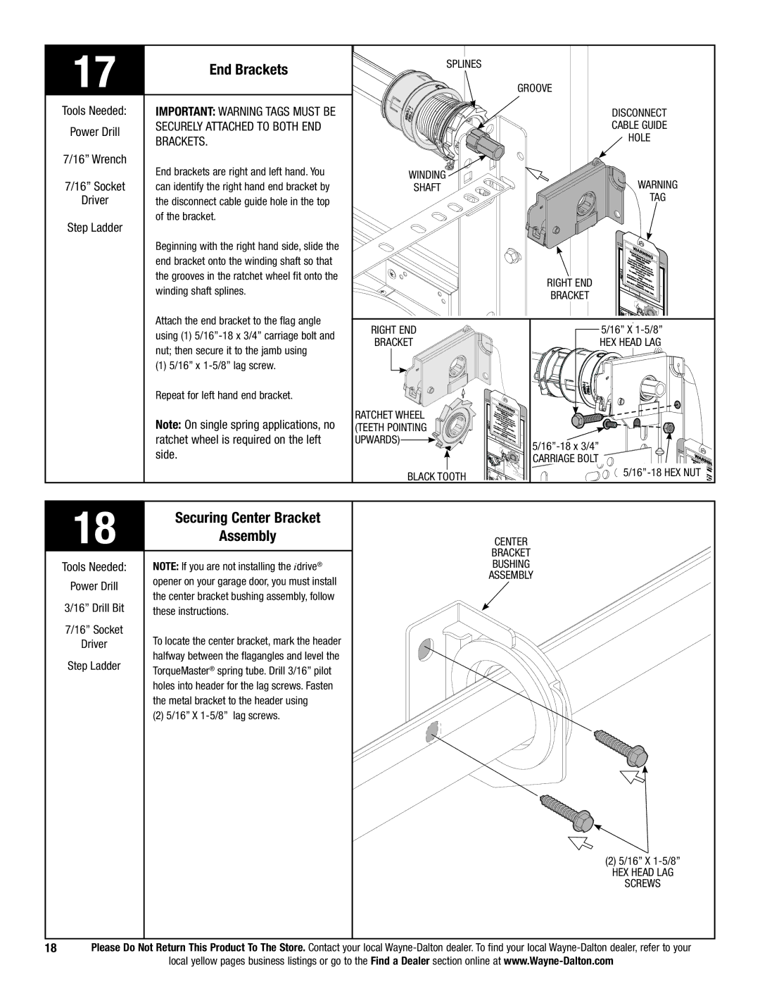
End brackets are right and left hand. You can identify the right hand end bracket by the disconnect cable guide hole in the top of the bracket.

Beginning with the right hand side, slide the end bracket onto the winding shaft so that the grooves in the ratchet wheel fit onto the winding shaft splines.

Winding 7/16” Wrench Shaft

Right End

Bracket

Warning

Tag

Use th


RNIN

G


thislabesele


Ra WA


chet

Br


E


To


XTR

a


avo


EMcket


fa


TENE SPis un


tal


id po

SIO


RINder

side of

fasteninjury, ssib

N.

G


ers


D

le

severe


until


fromO N

or


To


spr

ratOT re

m


ing( chet


ove


a


safe wn

s) a


b


ly uwou

re


rack


nd fol


nwind.

fully

et


inst


lowt re nd spr


D


allati


he

ad


ing

(s)


O N

OT


instruirectio


m

ctio ns

in


Drum


RE anu


nsl


sp


MO al.


/ownthes


Rat


e

VE T


er


chet


H

IS T


CablePawl and


Drum


AG.l

atchet


DISENGA


Drum


GED SIDE

VIEW


ment


DISENGA


GED UND


ERNEATH V

Attach the end bracket to the flag angle


IEW

Right End

5/16” x 1-5/8”

using (1) 5/16”-18 x 3/4” carriage bolt and

Bracket

Hex Head Lag

nut; then secure it to the jamb using


(1) 5/16” x 1-5/8” lag screw.


Repeat for left hand end bracket.


Use thesel


this labe


R WA


achet

R


To


Brack


Ratchet Wheel


un

der


side


fatalavoidTENSIOible se


of


injuryposs

SPRING.


fasteners from,


vere


Note: On single spring applications, no


until


DO NO

or


To


rat

T re


(Teeth pointing

EN


spring(s)chet

move


and

fosafelywnwo

are


unwiund. fullybracket


installationlowthereadnd spring(s)


DO

NOT


instdirec


in


ratchet wheel is required on the left


m ructiotion


D


upwards)


No


anual. ns/


t


rum


REMO

VE


he


Ratspace bet


owners


CachetblePawlD

and

THIS

TAG.


5/16”-18 x 3/4”


rumS


Ratchetmt


DI ENGAGED

SIDE VIEW


side.


tUhsiesthes


DIS


U


CARRIAGE Bolt

labe


ENGAGED

NDERNEATH VIEW


RacWA


RNINi


Rat t


EXhetB


Notspace


che

Pawl


Cable Drum


5/16”-18 HEX NUT

Runde


between


UPPER

Ra chet


Space


Black Tooth


CablePawl and


andbetween Rat


.ING


POSITION Drum


t


Tevere


non-


Cable Druchem

Pawl


indicates engagement


LOWER


rem


eetbra


18

Securing Center Bracket


Assembly


CENTER


BRACKET


Tools Needed:

NOTE: If you are not installing the idrive®


bushing


Power Drill

opener on your garage door, you must install


ASSEMBLY


the center bracket bushing assembly, follow


3/16” Drill Bit


these instructions.


7/16” Socket

To locate the center bracket, mark the header


Driver


Step Ladder

halfway between the flagangles and level the


TorqueMaster® spring tube. Drill 3/16” pilot


holes into header for the lag screws. Fasten


the metal bracket to the header using


(2) 5/16” x 1-5/8” lag screws.


(2) 5/16” x 1-5/8”


hex head lag


screws


18

Please Do Not Return This Product To The Store. Contact your local Wayne-Dalton dealer. To find your local Wayne-Dalton dealer, refer to your


local yellow pages business listings or go to the Find a Dealer section online at www.Wayne-Dalton.com


Page 18
Image 18
Wayne-Dalton 9700 End Brackets, Securing Center Bracket, Assembly, 7/16” Wrench 7/16” Socket Driver Step Ladder, side