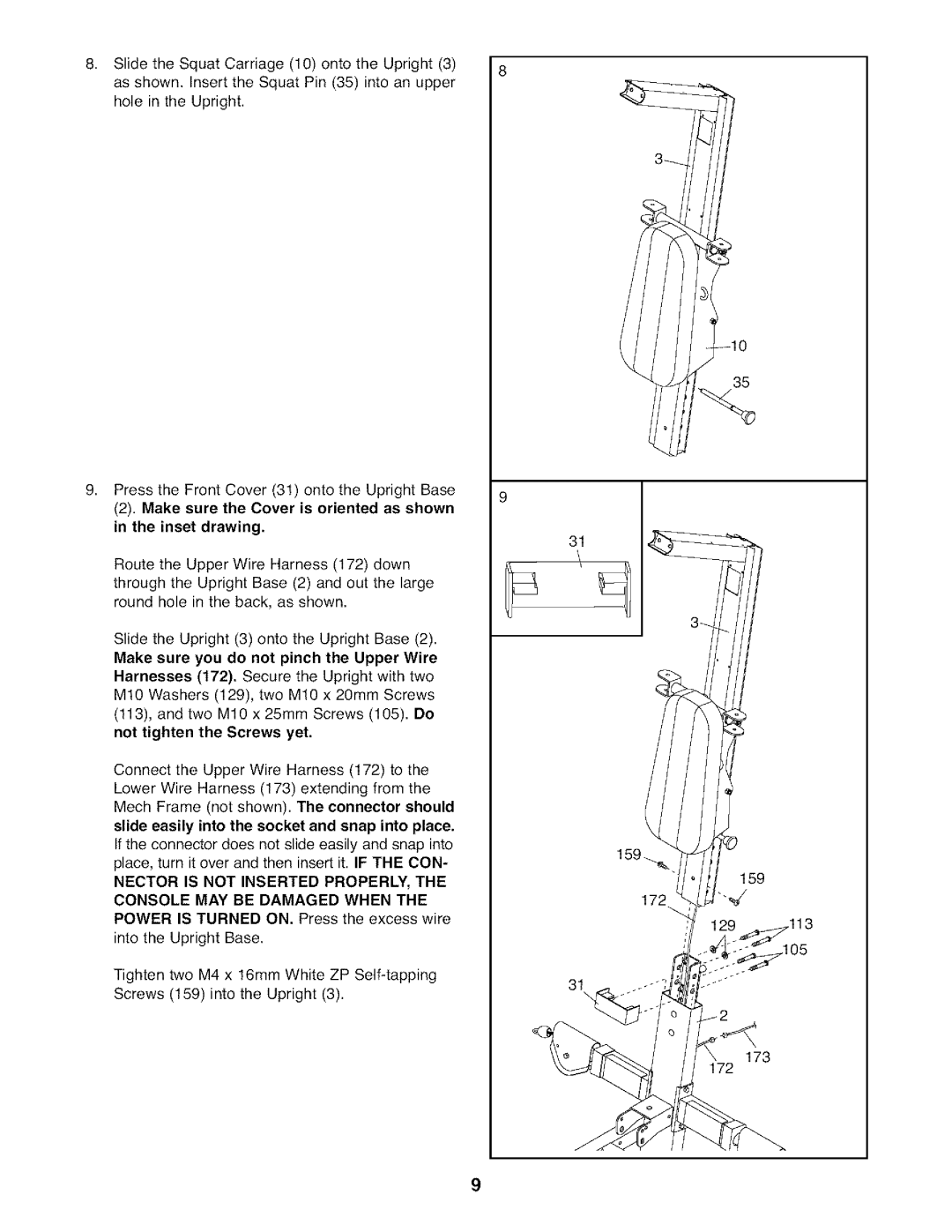
8. Slide | the Squat Carriage (10) onto the Upright (3) | 8 |
as shown. Insert the Squat Pin (35) into an upper |
| |
hole | in the Upright. |
|
35
9, | Press the Front Cover (3!) onto the Upright Base | 9 | |
| |||
| (2). Make sure the Cover is oriented as shown | ||
|
| ||
| in the inset drawing. | 31 | |
|
|
| |
| Route the Upper Wire Harness (172) down |
| |
| through the Upright Base (2) and out the large |
| |
| round hole in the back, as shown. |
| |
| Slide the Upright (3) onto the Upright Base (2). |
| |
| Make sure you do not pinch the Upper Wire |
| |
| Harnesses (t72). Secure the Upright with two |
| |
| M!0 Washers | (129), two M10 x 20mm Screws |
|
| (113), and two | M10 x 25ram Screws (105). Do |
|
| not tighten the Screws yet. |
| |
| Connect the Upper Wire Harness (172) to the |
| |
| Lower Wire Harness (173) extending from the |
| |
| Mech Frame (not shown). The connector should |
| |
| slide easily into the socket and snap into place. |
| |
| If the connector does not slide easily and snap into |
| |
| place, turn it over and then insert it. IF THE CON- |
| |
| NECTOR IS NOT INSERTED PROPERLY, THE |
| |
| CONSOLE MAY BE DAMAGED WHEN THE |
| |
| POWER IS TURNED ON. Press the excess wire |
| |
| into the Upright | Base. |
|
159
113
Tighten two M4 x !6mm White ZP
Screws (159) into the Upright (3).
31
173
172
9
