MEASURING GAS PRESSURE
Gas pressure is measured in Inches of Water Column Pressure (WCP). It takes 28" WCP to equal one pound
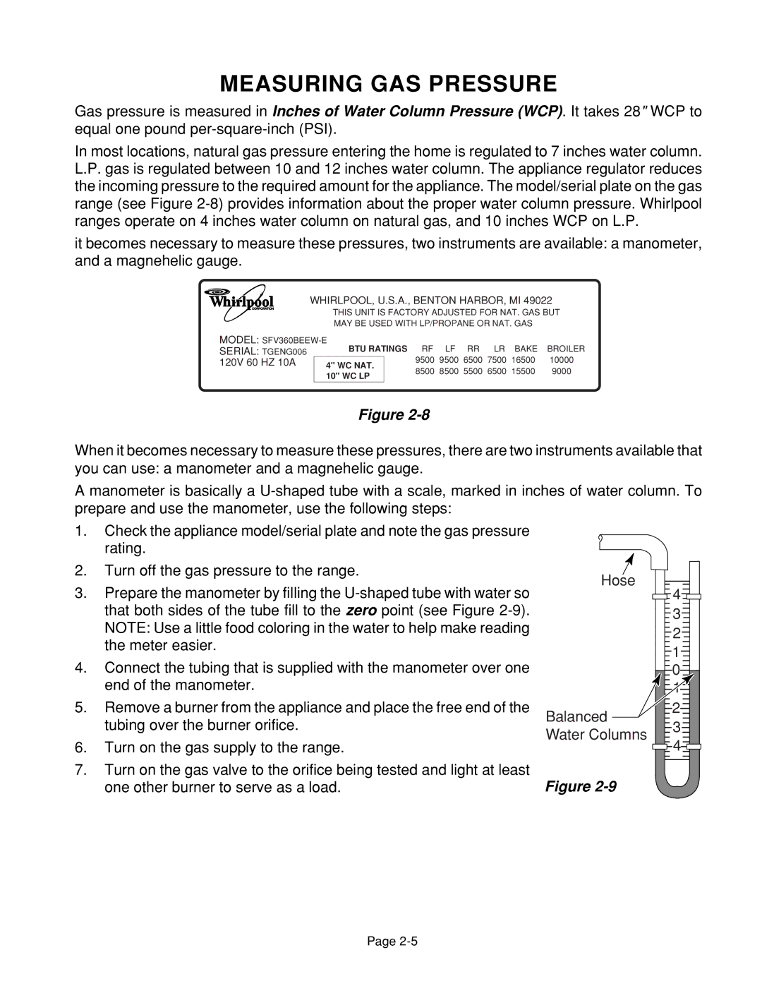
In most locations, natural gas pressure entering the home is regulated to 7 inches water column. L.P. gas is regulated between 10 and 12 inches water column. The appliance regulator reduces the incoming pressure to the required amount for the appliance. The model/serial plate on the gas range (see Figure
it becomes necessary to measure these pressures, two instruments are available: a manometer, and a magnehelic gauge.
WHIRLPOOL, U.S.A., BENTON HARBOR, MI 49022
THIS UNIT IS FACTORY ADJUSTED FOR NAT. GAS BUT
MAY BE USED WITH LP/PROPANE OR NAT. GAS
MODEL: |
|
|
|
|
|
| ||
SERIAL: TGENG006 | BTU RATINGS RF | LF | RR | LR | BAKE | BROILER | ||
120V 60 HZ 10A | 4" WC NAT. | 9500 | 9500 | 6500 | 7500 | 16500 | 10000 | |
8500 | 8500 | 5500 | 6500 | 15500 | 9000 | |||
| 10" WC LP | |||||||
|
|
|
|
|
|
| ||
Figure
When it becomes necessary to measure these pressures, there are two instruments available that you can use: a manometer and a magnehelic gauge.
A manometer is basically a
1.Check the appliance model/serial plate and note the gas pressure rating.
2.Turn off the gas pressure to the range.
3.Prepare the manometer by filling the
4.Connect the tubing that is supplied with the manometer over one end of the manometer.
5.Remove a burner from the appliance and place the free end of the tubing over the burner orifice.
6.Turn on the gas supply to the range.
7.Turn on the gas valve to the orifice being tested and light at least one other burner to serve as a load.
Hose | 4 | |
| ||
| 3 | |
| 2 | |
| 1 | |
| 0 | |
| 1 | |
Balanced | 2 | |
3 | ||
Water Columns | ||
4 | ||
|
Figure
Page