The Cooktop Burner Assembly controls the combustion of gas and directs its flame (see Figure
1.An Air Shutter to control the amount of primary air to be mixed with the gas.
2.A Venturi to provide a pathway for gas to flow to the burner from the orifice. Air enters the burner through the venturi tube, and is used as a pathway for gas, as well as an area for gas and air to be mixed together for combustion.
3.A Burner Head to provide an exit for gas so it can be ignited. The exits are normally holes, or slots, called “burner ports.”
Burner Head
Figure
Air Shutter
Venturi
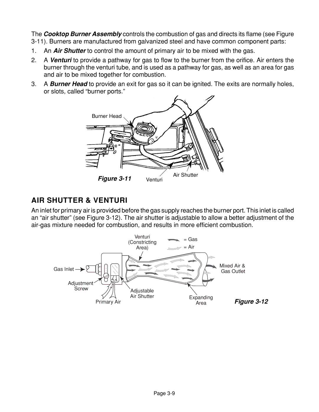
AIR SHUTTER & VENTURI
An inlet for primary air is provided before the gas supply reaches the burner port. This inlet is called an “air shutter” (see Figure
| Venturi | = Gas |
|
| (Constricting |
| |
| = Air |
| |
| Area) |
| |
Gas Inlet |
|
| Mixed Air & |
|
| Gas Outlet | |
|
|
| |
Adjustment |
|
|
|
Screw | Adjustable |
|
|
|
|
| |
| Air Shutter | Expanding | Figure |
| Primary Air | Area |
Page