Refer to Figure
CONVENTIONAL BURNER
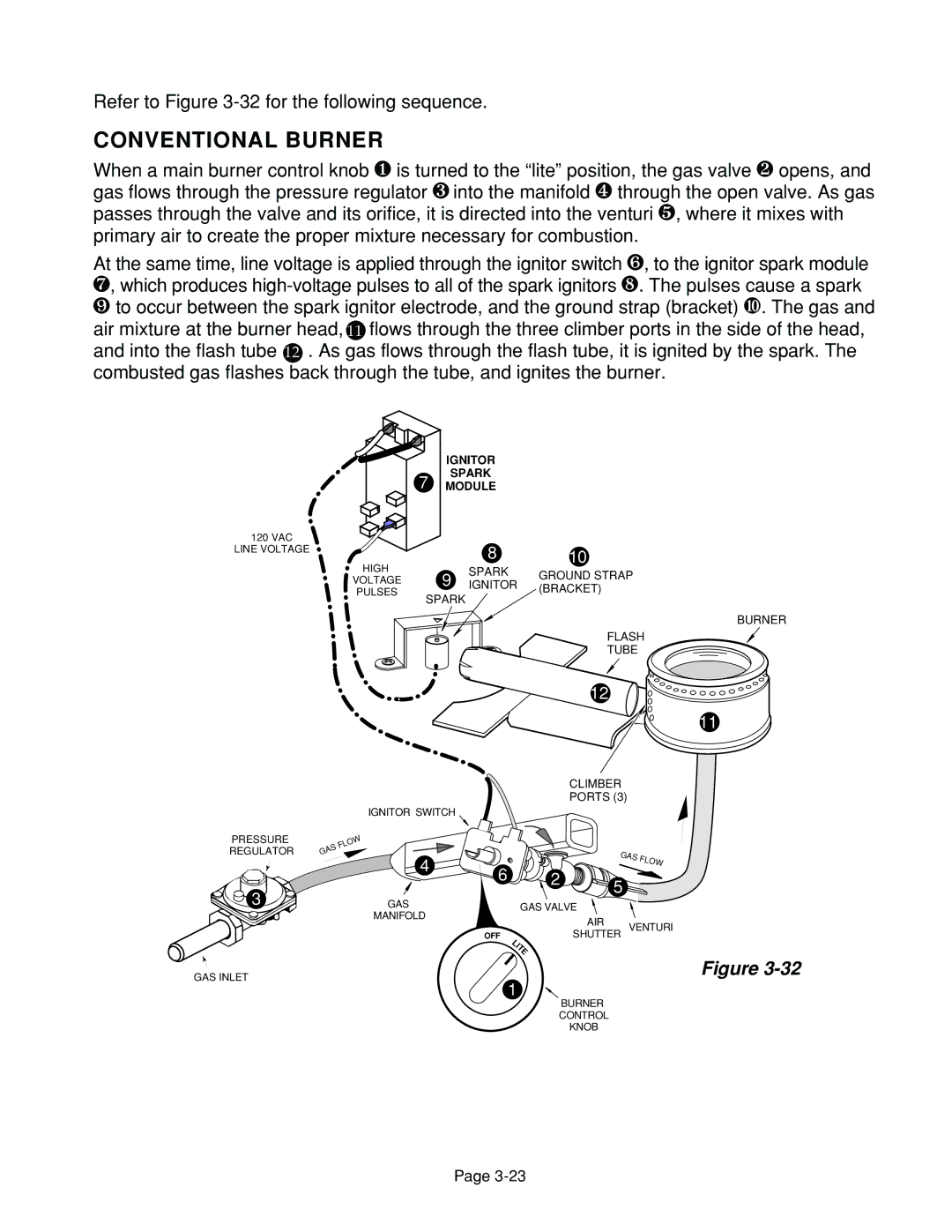
When a main burner control knob q is turned to the “lite” position, the gas valve r opens, and gas flows through the pressure regulator s into the manifold t through the open valve. As gas passes through the valve and its orifice, it is directed into the venturi u, where it mixes with primary air to create the proper mixture necessary for combustion.
At the same time, line voltage is applied through the ignitor switch v, to the ignitor spark module w, which produces
yto occur between the spark ignitor electrode, and the ground strap (bracket) z. The gas and air mixture at the burner head, 11 flows through the three climber ports in the side of the head, and into the flash tube 12 . As gas flows through the flash tube, it is ignited by the spark. The combusted gas flashes back through the tube, and ignites the burner.
120 VAC
LINE VOLTAGE
HIGH
VOLTAGE
PULSES
| IGNITOR |
|
7 | SPARK |
|
MODULE |
| |
| 8 | 10 |
9 | SPARK | GROUND STRAP | |
IGNITOR | |||
(BRACKET) | |||
SPARK |
| ||
|
|
PRESSURE
REGULATOR
![]() 3
3
IGNITOR SWITCH
FLOW
GAS
4
GAS
MANIFOLD
BURNER
FLASH
TUBE
12![]()
11
CLIMBER
PORTS (3)
GAS FLOW
6 | 2 | 5 |
|
|
|
| |
| GAS VALVE |
| |
|
| AIR | VENTURI |
OFF | LITE | SHUTTER | |
|
|
| |
GAS INLET
Figure
1
BURNER
CONTROL
KNOB
Page