ELECTRONIC IGNITION SYSTEM
OPERATION
The Electronic Ignition System performs the same function as the standing pilot ignition system. However, instead of using a standing pilot flame to ignite the main burners, a spark from a surface burner ignitor is used.
The electronic ignition system consists of the following components:
1.Ignitor Switches
2.Ignitor Spark Module
3.Surface Burner Ignitors (electrodes)
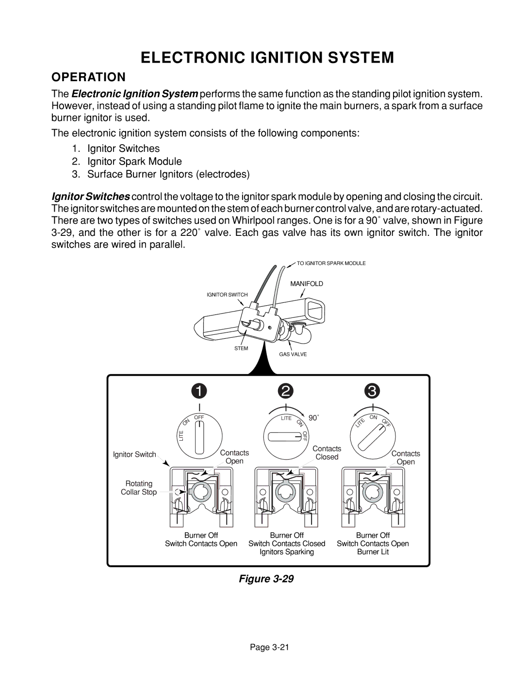
Ignitor Switches control the voltage to the ignitor spark module by opening and closing the circuit. The ignitor switches are mounted on the stem of each burner control valve, and are
![]() TO IGNITOR SPARK MODULE
TO IGNITOR SPARK MODULE
MANIFOLD
IGNITOR SWITCH
STEM
GAS VALVE
123
OFF | LITE | 90˚ |
ON |
| ON |
LITE |
| OFF |
Contacts
Ignitor SwitchContactsClosed
Open
Rotating
Collar Stop ![]()
LITE | ON |
OFF |
Contacts
Open
Burner Off | Burner Off | Burner Off |
Switch Contacts Open | Switch Contacts Closed | Switch Contacts Open |
| Ignitors Sparking | Burner Lit |
Figure
Page