GAS VALVE
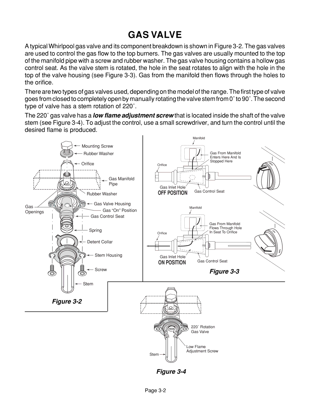
A typical Whirlpool gas valve and its component breakdown is shown in Figure
There are two types of gas valves used, depending on the model of the range. The first type of valve goes from closed to completely open by manually rotating the valve stem from 0˚ to 90˚. The second type of valve has a stem rotation of 220˚.
The 220˚ gas valve has a low flame adjustment screw that is located inside the shaft of the valve stem (see Figure
| Manifold |
Mounting Screw |
|
Rubber Washer | Gas From Manifold |
| Enters Here And Is |
Orifice | Stopped Here |
Orifice |
| Gas Manifold |
|
|
| Pipe | Gas Inlet Hole |
|
|
| Gas Control Seat | |
| Rubber Washer | OFF POSITION | |
|
| ||
Gas | Gas Valve Housing |
| Manifold |
Gas “On” Position |
| ||
Openings |
|
| |
Gas Control Seat |
|
| |
|
|
| |
|
|
| Gas From Manifold |
| Spring |
| Flows Through Hole |
| Orifice | In Seat To Orifice | |
|
| ||
| Detent Collar |
|
|
| Stem Housing | Gas Inlet Hole |
|
|
| Gas Control Seat | |
|
| ON POSITION | |
|
|
|
Screw | Figure |
| |
Stem |
|
Figure
220˚ Rotation
Gas Valve
Low Flame
Adjustment Screw
Stem ![]()
OFF
On
OFF
Figure
Page