MANUAL STORAGE TUBE INSTALLATION
The manual storage tube may be supplied in either of the following styles.
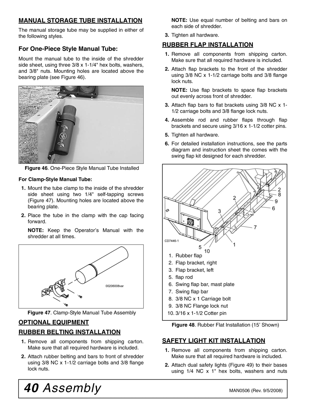
For One-Piece Style Manual Tube:
Mount the manual tube to the inside of the shredder side sheet, using three 3/8 x
Figure 46. One-Piece Style Manual Tube Installed
For Clamp-Style Manual Tube:
1.Mount the tube clamp to the inside of the shredder side sheet using two 1/4"
2.Place the tube in the clamp with the cap facing forward.
NOTE: Keep the Operator’s Manual with the shredder at all times.
Figure 47. Clamp-Style Manual Tube Assembly
OPTIONAL EQUIPMENT
RUBBER BELTING INSTALLATION
1.Remove all components from shipping carton. Make sure that all required hardware is included.
2.Attach rubber belting and bars to front of shredder using 3/8 NC x
NOTE: Use equal number of belting and bars on each side of shredder.
3.Tighten all hardware.
RUBBER FLAP INSTALLATION
1.Remove all components from shipping carton. Make sure that all required hardware is included.
2.Attach flap brackets to the front of the shredder using 3/8 NC x
NOTE: Use flap brackets to space flap brackets out evenly across front of shredder.
3.Attach flap bars to flat brackets using 3/8 NC x 1- 1/2 carriage bolts and 3/8 flange lock nuts.
4.Assemble rod and rubber flaps through flap brackets and secure using 3/16 x
5.Tighten all hardware.
6.For detailed installation instructions, see the parts diagram and instruction sheet the comes with the swing flap kit designed for each shredder.
1.Rubber flap
2.Flap bracket, right
3.Flap bracket, left
5.flap rod
6.Swing flap bar, mast plate
7.Swing flap bar
8.3/8 NC x 1 Carriage bolt
9.3/8 NC Flange lock nut
10. 3/16 x
Figure 48. Rubber Flat Installation (15’ Shown)
SAFETY LIGHT KIT INSTALLATION
1.Remove all components from shipping carton. Make sure that all required hardware is included.
2.Attach dual safety lights (Figure 49) to their bases using 1/4 NC x 1" hex bolts, washers and nuts
40 Assembly | MAN0506 (Rev. 9/5/2008) |
|
|